This chapter covers the following topics that you will need to master as a CCNA:
•
Point-to-Point Leased Lines
This section covers basic operation and terminology
used with point-to-point leased lines. Configuration and debugging of PPP, HDLC,
and LAPB are shown as well.
•
Frame Relay Protocols
Frame Relay is one of the most popular WAN services
today. The concepts and terminology used with Frame Relay are discussed in detail,
including the use of Frame Relay DLCIs.
•
Frame Relay Configuration
Several variations for Frame Relay configuration
exist. This section covers the default style of configuration and then discusses the
various options. The text also details design choices of how to assign IP subnet and
IPX network numbers.
•
ISDN Protocols and Design
As with Frame Relay, ISDN has its own set of
concepts, terms, and acronyms. This section covers the protocol basics.
•
Dial-on-Demand Routing and ISDN Configuration
Dial-on-demand routing
(DDR) is the name for the IOS features that relate to dialing other routers to add new
links for routing packets. This section covers DDR concepts and configuration, with
ISDN configuration information interspersed.
•
A Comparison of WAN Options
This section gives a brief summary of the WAN
options covered in this chapter.
C
H
A
P
T
E
R
8
WAN Protocols and Design
CCNAs deal with both permanent and dialed WAN connections on routers on a regular
basis. In fact, with the pervasiveness of LAN switches in modern buildings, more
frequently the issues relating to router installation and troubleshooting are about WAN
connections.
This chapter is rather long; if you plan to read the entire chapter, you might want to treat it
as three separate sections. These three major sections are outlined in Table 8-1. The first of
these topical areas discusses point-to-point leased lines. The second covers Frame Relay,
and the last details DDR and ISDN.
Cisco expects CCNAs to be able to configure, verify, and troubleshoot WAN connections.
The conceptual material in this chapter is important, but it is Cisco’s desire that the exam
serve as proof that you are able to make this stuff work. Focusing on the command
examples and scenarios will help.
How to Best Use This Chapter
By taking the following steps, you can make better use of your study time:
•
Keep your notes and the answers for all your work with this book in one place, for
easy reference.
•
Take the “Do I Know This Already?” quiz, and write down your answers. Studies
show that retention is significantly increased through writing down facts and
concepts, even if you never look at the information again.
•
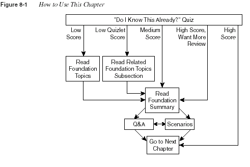
Use the diagram in Figure 8-1 to guide you to the next step.
516
Chapter 8: WAN Protocols and Design

“Do I Know This Already?” Quiz
The purpose of the “Do I Know This Already?” quiz is to help you decide what parts of this
chapter to use. If you already intend to read the entire chapter, you do not necessarily need to
answer these questions now.
This 12-question quiz helps you choose how to spend your limited study time. The quiz is
sectioned into three smaller four-question “quizlets,” which correspond to the three major
headings in the chapter. Figure 8-1 outlines suggestions on how to spend your time in this
chapter. Use Table 8-1 to record your score.
Table 8-1
Scoresheet for Quiz and Quizlets
Quizlet
Number
Foundation Topics Sections Covering
These Questions Questions Score
1 Point-to-Point Leased Lines 1 to 4
2 Frame Relay Protocols
Frame Relay Configuration
5 to 8
3 ISDN Protocols and Design
Dial-on-Demand Routing and ISDN
Configuration
9 to 12
All questions 1 to 12
“Do I Know This Already?” Quiz
517
1
Can PPP perform dynamic assignment of IP addresses? If so, is the feature always
enabled?
___________________________________________________________________
___________________________________________________________________
___________________________________________________________________
2
Create a configuration to enable PPP on serial 0 for IP and IPX. Make up IP and IPX
Layer 3 addresses as needed.
___________________________________________________________________
___________________________________________________________________
___________________________________________________________________
3
CHAP configuration uses names and passwords. Given Routers A and B, describe what
names and passwords must match in the respective CHAP configurations.
___________________________________________________________________
___________________________________________________________________
___________________________________________________________________
4
What field has Cisco added to the HDLC header, making it proprietary?
___________________________________________________________________
___________________________________________________________________
___________________________________________________________________
5
Explain the purpose of Inverse ARP. Explain how Inverse ARP uses Frame Relay
broadcasts.
___________________________________________________________________
___________________________________________________________________
___________________________________________________________________
6
Would a Frame Relay switch connected to a router behave differently if the IETF option
were deleted from the encapsulation
frame-relay ietf
command on that attached router?
Would a router on the other end of the VC behave any differently if the same change were
made?
___________________________________________________________________
___________________________________________________________________
___________________________________________________________________
518
Chapter 8: WAN Protocols and Design
7
What
show
command will tell you the time that a PVC became active? How does the
router know what time the PVC came active?
__________________________________________________________________
__________________________________________________________________
__________________________________________________________________
8
What
debug
options will show Inverse ARP messages?
__________________________________________________________________
__________________________________________________________________
__________________________________________________________________
9
What does the acronym LAPD stand for? Is it used as the Layer 2 protocol on dialed ISDN
bearer channels? If not, what is used?
__________________________________________________________________
__________________________________________________________________
__________________________________________________________________
10
Define the term
reference point
. List two examples of reference points.
__________________________________________________________________
__________________________________________________________________
__________________________________________________________________
11
Describe the decision process performed by the IOS to attempt to dial a connection using
legacy DDR.
__________________________________________________________________
__________________________________________________________________
__________________________________________________________________
12
If packets from 10.1.1.0/24 were “interesting” in relation to DDR configuration such that
packets from 10.1.1.0/24 would cause a DDR connection out an interface BRI0, list the
configuration commands that would make the IOS think that those packets were
interesting on BRI0.
__________________________________________________________________
__________________________________________________________________
__________________________________________________________________
“Do I Know This Already?” Quiz
519
The answers to the quiz are found in Appendix A, “Answers to the ‘Do I Know This Already?’
Quizzes and Q&A Sections,” on page 768. The suggested choices for your next step are as
follows:
•
6 or less overall score
—Read the entire chapter. This includes the “Foundation Topics”
and “Foundation Summary” sections, the Q&A section, and the scenarios at the end of the
chapter.
•
2 or less on any quizlet
—Review the subsection(s) of the “Foundation Topics” part of
this chapter, based on the following list. Then move into the “Foundation Summary”
section, the quiz, and the scenarios at the end of the chapter.
•
7, 8, or 9 overall score
—Begin with the “Foundation Summary” section, and then go to
the Q&A section and the scenarios at the end of the chapter.
•
10 or more overall score
—If you want more review on these topics, skip to the
“Foundation Summary” section and then go to the Q&A section and the scenarios at the
end of the chapter. Otherwise, move to the next chapter.
520
Chapter 8: WAN Protocols and Design
Foundation Topics
Point-to-Point Leased Lines
WAN protocols used on point-to-point serial links provide the basic function of delivery of data
across that one link. As a CCNA, you will be required to understand and configure a variety of
protocols used on point-to-point links, including Link Access Procedure Balanced (LAPB),
High-Level Data Link Control (HDLC), and Point-to-Point Protocol (PPP). Each of these WAN
protocols has the following functions in common:
•
LAPB, HDLC, and PPP provide for delivery of data across a single point-to-point serial
link.
•
LAPB, HDLC, and PPP deliver data on synchronous serial links. (PPP supports
asynchronous functions as well.)
Framing is one core feature of any synchronous serial data link protocol. Each of these
protocols defines framing so that receiving stations know where the beginning of the frame is,
what address is in the header, and the point at which the packet begins. By doing so, the router
receiving data can distinguish between idle frames and data frames. Synchronous links, rather
than asynchronous links, are typically used between routers.
Synchronous
simply means that there is an imposed time ordering at the sending and receiving
ends of the link. Essentially, the sides agree to a certain speed, but because it is very expensive
to build devices that can truly operate at exactly the same speed, the devices adjust their rates
to match a clock source. The process works almost like the scenes in spy novels, when the spies
synchronize their watches; in this case, the watches or clocks are synchronized automatically
multiple times per minute. Unlike asynchronous links, in which no bits are sent during idle
times, synchronous data links define idle frames. These frames do nothing more than provide
plenty of signal transitions so that clocks can be adjusted on the receiving end, consequently
maintaining synchronization.
Before describing the features of these data link protocols, a brief reference to some popularly
used WAN terminology is useful. Table 8-2 lists the terms.
Table 8-2
WAN Terminology
Term Definition
Synchronous The imposition of time ordering on a bit stream. More
practically speaking, a device will try to use the same speed
as another on the other end of a serial link. However, by
examining transitions between voltage states on the link, the
device can notice slight variations in the speed on each end so
that it can adjust its speed.
Point-to-Point Leased Lines
521
Three key attributes help to differentiate among these synchronous serial data link protocols
(LAPB, HDLC, and PPP):
•
Whether the protocol supports synchronous communications, asynchronous
communications, or both.
•
Whether the protocol provides error recovery. (The LAPB, HDLC, and PPP protocols all
provide error detection.)
Asynchronous The lack of an imposed time ordering on a bit stream. More
practically speaking, both sides agree to the same speed, but
there is no check or adjustment of the rates if they are slightly
different. However, because only 1 byte per transfer is sent,
slight differences in clock speed are not an issue. A start bit is
used to signal the beginning of a byte.
Clock source The device to which the other devices on the link adjust their
speed when using synchronous links.
DSU/CSU Data Services Unit and Channel Services Unit. This is used on
digital links as an interface to the telephone company in the
United States. Routers typically use a short cable from a serial
interface to a DSU/CSU, which is attached to the line from the
telco with a similar configuration at the other router on the
other end of the link. The routers use their attached DSU/CSU
as the clock source.
Telco Telephone company.
4-wire circuit A line from the telco with four wires, comprised of two
twisted-pair wires. Each pair is used to send in one direction,
so a 4-wire circuit allows full-duplex communication.
2-wire circuit A line from the telco with two wires, comprised of one
twisted-pair wire. The pair is used to send in only one direction
at a time, so a 2-wire circuit allows only half-duplex
communication.
T/1 A line from the telco that allows transmission of data at
1.544Mbps. This can be used with a T/1 multiplexor.
T/1 mux A multiplexor that separates the T/1 into 24 different 64kbps
channels. In the United States, one of every 8 bits in each
channel can be used by the telco so that the channels are
effectively 56kbps channels.
E/1 Like a T/1, but in Europe. It uses a rate of 2.048Mbps and 32
64kbps channels.
Table 8-2
WAN Terminology (Continued)
Term Definition
522
Chapter 8: WAN Protocols and Design
•
Whether an architected Protocol Type field exists. In other words, the protocol
specifications define a field in the header that identifies the type of packet contained in the
data portion of the frame.
First, a few words about the criteria used to compare these WAN protocols might prove helpful.
Synchronous protocols allow more throughput over a serial link than asynchronous protocols
do. However, asynchronous protocols require less expensive hardware because there is no need
to watch transitions and adjust the clock rate. For links between routers, synchronous links are
typically desired and used. All the protocols covered in this section support synchronous links.
Another comparison criteria is error recovery. Error recovery is covered in detail in Chapter 3,
“OSI Reference Model & Layered Communication,” but a brief review is in order here. All the
data link protocols described here use a field in the trailer, usually called the frame check
sequence (FCS), that is used to verify whether bit errors occurred during transmission of the
frame. If so, the frame is discarded. Error recovery is the process that causes retransmission of
the lost frame(s); error recovery may be performed by the data link protocol or a higher-layer
protocol, or error recovery may not be performed at all. Regardless, all WAN data link protocols
perform error detection, which involves noticing the error and discarding the frame.
Finally, the definition and use of an architected Protocol Type field is the final criteria for
comparison. As described in more detail in Chapter 3, each data link protocol that supports
multiple network layer protocols needs a method of defining the type of packet encapsulated
inside the WAN data link frame. If such a field is part of the protocol specification, it is
considered “architected”—in other words, specified in the protocol. If Cisco must add some
other header information to create a Protocol Type field, then that type field is not considered
to be architected.
Table 8-3 lists these point-to-point data link protocols and their attributes. (For a review of the
Protocol Type field, refer to Chapter 3.)
Table 8-3
Point-to-Point Data Link Protocol Attributes
Protocol
Error
Correction?
Architected
Type Field? Other Attributes
Synchronous Data
Link Control
(SDLC)
Yes None SDLC supports multipoint links; it
assumes that the SNA header occurs
after the SDLC header.
Link Access
Procedure
Balanced (LAPB)
Yes None Spec assumes a single configurable
protocol after LAPB. LAPB is used
mainly with X.25. Cisco uses a
proprietary type field to support
multiprotocol traffic.
Link Access
Procedure on the D
channel (LAPD)
No No LAPD is not used between routers,
but is used on the D channel from
router to ISDN switch for signaling.
Point-to-Point Leased Lines
523
Note:
Be careful not to confuse LAPB and LAPD. The D can help remind you that it is for an ISDN D channel, but
don’t let that make you think that the B is for an ISDN B channel.
HDLC and PPP Configuration
One common task for CCNAs is to enable an appropriate point-to-point data link protocol.
The configuration is straightforward, with LAPB being the exception. (Be sure to configure
the same WAN data link protocol on each end of the serial link. Otherwise, the routers will
misinterpret the incoming frames, and the link will not work.) Tables 8-4 and 8-5 summarize
the configuration commands and the
show
and
debug
commands used for HDLC and PPP
configuration.
High-Level Data
Link Control
(HDLC)
No No HDLC serves as Cisco’s default on
serial links. Cisco uses a proprietary
type field to support multiprotocol
traffic.
Point-to-Point
Protocol (PPP)
Enables the user to
choose whether
error correction is
performed;
correction uses
LAPB
Yes PPP was meant for multiprotocol
interoperability from its inception,
unlike all the others. PPP also
supports asynchronous
communication.
Table 8-4
PPP and HDLC Configuration Commands
Command Configuration Mode
encapsulation
{
hdlc
|
ppp
|
lapb
} Interface subcommand
compress
[
Predictor
|
stac
|
mppc
[
ignore-pfc
]]
Interface subcommand
Table 8-5
Point-to-Point Related
show
and
debug
Commands
Command Function
show interface
Lists statistics and details of interface configuration,
including the encapsulation type.
show compress
Lists compression ratios.
show process
Lists processor and task utilization. Is useful in watching
for increased utilization due to compression.
Table 8-3
Point-to-Point Data Link Protocol Attributes (Continued)
Protocol
Error
Correction?
Architected
Type Field? Other Attributes
524
Chapter 8: WAN Protocols and Design
Example 8-1 lists configuration for HDLC, followed by the changed configuration for a
migration to PPP. Assume that Router A and Router B have a serial link attached to their serial
0 ports, respectively.
Changing serial encapsulations in configuration mode is tricky compared to some other
configuration commands in a Cisco router. In Example 8-1, converting back to HDLC (the
default) is done with the
encapsulation hdlc
command, not by using a command such as
no
encapsulation ppp
. Additionally, any other interface subcommands that are pertinent only to
PPP are also removed when the
encapsulation hdlc
command is used.PPP provides several other features in addition to synchronization and framing. The features
fall into two categories: those needed regardless of the Layer 3 protocol sent across the link, and
those particular to each Layer 3 protocol.
The PPP Link Control Protocol (LCP) provides the base features needed regardless of the Layer
3 protocol sent across the link. A series of PPP control protocols, such as IP Control Protocol
(IPCP), provide features for a particular Layer 3 protocol to function well across the link. For
example, IPCP provides for IP address assignment; this feature is used extensively with Internet
dialup connections today.
Only one LCP is needed per link, but multiple control protocols are needed. If a router is
configured for IPX, AppleTalk, and IP on a PPP serial link, the router configured for PPP
encapsulation automatically tries to bring up the appropriate control protocols for each Layer 3
protocol. Table 8-6 summarizes the features of LCP, which performs functions not specific to a
particular Layer 3 protocol.
Example 8-1
Configuration for PPP and HDLCRouter A Router B
Interface serial 0 Interface serial 0
encapsulation ppp encapsulation ppp
. .
. later, changed to... . later, changed to...
. .
interface serial 0 interface serial 0
encapsulation hdlc encapsulation hdlc
Table 8-6
PPP LCP FeaturesFunction
Name of LCP
Feature Description
Error detection Link Quality
Monitoring (LQM)
PPP can take down a link based on the percentage of
errors on the link. LQM exchanges statistics about lost
packets versus sent packets in each direction; when
compared to packets and bytes sent, this yields a
percentage of errored traffic. The percentage of loss that
causes a link to be taken down is enabled and defined
by a configuration setting.
Point-to-Point Leased Lines
525Error Detection and Looped Link Detection
Error detection and looped link detection are two key features of PPP. Looped link detection
allows for faster convergence when a link fails because it is looped. (Links are typically looped
for testing purposes.) When this occurs, a router continues to receive the looped Cisco
proprietary keepalive messages, so the router might not think that the link has failed. For
instance, the absence of routing updates from a neighbor for a certain length of time is used to
drive convergence. Waiting on such an event when the link is looped increases convergence
time.
Looped link detection defeats this problem using a PPP feature called
magic numbers. Therouter sends PPP messages instead of keepalives; these messages include a magic number,
which is different on each router. If a line is looped, the router receives a message with its own
magic number instead of getting a message with the magic number identifying the router on the
other end of the link. A router receiving its own magic number knows that the frame it sent has
been looped back. If configured to do so, the router can take down the interface, which speeds
convergence.
Error detection (not error recovery) is accomplished by a PPP feature called
Link QualityMonitoring (LQM).
PPP at each end of the link sends messages describing the number ofcorrectly received packets and bytes. This is compared to the number of packets and bytes sent
to calculate a percentage loss. The router can be configured to take down the link after a
configured error rate has been exceeded so that future packets are sent over a longer—but
hopefully better—path.
Looped link
detection
Magic number Using a magic number, routers send messages to each
other with a different magic number. If you ever receive
your own magic number, the link is looped. A
configuration setting determines whether the link
should be taken down when looped.
Authentication PAP and CHAP Mostly used on dial links, PAP and CHAP can be used
to authenticate the device on the other end of the link.
Compression STAC and Predictor This is software compression.
Multilink support Multilink PPP Fragments of packets are load-balanced across multiple
links. This feature is more often used with dial. The
section “Multilink PPP,” later in the chapter, covers this
concept in greater detail.
Table 8-6
PPP LCP Features (Continued)Function
Name of LCP
Feature Description
526
Chapter 8: WAN Protocols and DesignCompression
Compression can be performed on LAPB, HDLC, and PPP point-to-point serial links. The goal
of compression is to reduce the number of bytes sent across the link. However, there is a price
to pay for compression—CPU cycles and possibly increased latency for the packets. The
following list summarizes the trade-offs when considering whether to use compression:
•
More processing is required on the router to compress each frame, as compared with nocompression.
•
Latency per frame will increase because of the processing required.•
Latency per frame will decrease in cases when the uncompressed packets have waited inthe output queue due to link congestion. With the compressed frames, however, the queue
is shorter.
•
Link utilization will decrease.So, in cases in which the leased lines are expensive or a faster line cannot be justified, then
compression can be desirable. However, care must be taken to avoid excessive CPU utilization.
Cisco recommends avoiding sustained CPU utilization exceeding between 40 and 65 percent,
depending on the platform.
Compression can be performed in software or in hardware. Any IOS router can perform LAPB,
HDLC, and PPP link compression in software; when software compression is used, CPU
utilization is impacted. For hardware compression, either a VIP2 card or a Compression Service
Adapter (CSA) on a 72xx or 75xx series router is required. When hardware compression is
performed, the CPU is not affected.
Several compression algorithms are available in the IOS to perform PPP compression: the
STAC
, Predictor, and Microsoft Point-to-Point Compression algorithm (MPPC). The details ofthe algorithms are beyond the scope of the CCNA exam. However, the MPPC algorithm and
protocols can be used between a router and a PC on a dial connection when compression is
desired.
HDLC supports compression only with the STAC algorithm. LAPB supports STAC and
Predictor algorithms. Only PPP supports the MPPC algorithm. Table 8-7 summarizes the
support for each type.
Table 8-7
Compression Types for Serial EncapsulationsEncapsulation Type Type of Compression Supported in IOS
PPP STAC, Predictor, MPPC
LAPB STAC, Predictor
HDLC STAC
Point-to-Point Leased Lines
527Configuration for PPP and HDLC compression is very straightforward. Consider Figure 8-2
and Example 8-2. A pair of routers is using a serial link and is configured for PPP STAC
compression.

The configuration in Example 8-2, compared to a scenario without using compression, simply
requires that the interfaces on each end of the link have the same compression algorithm
enabled with the
compress command. The show compress command in the example does nothave any particularly interesting numbers, mainly because of the lack of traffic in the network.
The 1-, 5-, and 10-minute averages are the transmit and receive compression ratios, which are
particularly useful for discovering whether the compression is effective. In fact, if most of the
Example 8-2
PPP Compression Configuration and Verification! Seville’s Pertinent configuration:
!
interface Serial1
ip address 10.1.11.253 255.255.255.0
encapsulation ppp
compress stac
! Mars’s Pertinent configuration:
!
interface Serial1
ip address 10.1.11.1 255.255.255.0
encapsulation ppp
compress stac
!
Seville#
show compressSerial1
Software compression enabled
uncompressed bytes xmt/rcv 10710562/11376835
1 min avg ratio xmt/rcv 2.773/2.474
5 min avg ratio xmt/rcv 4.084/3.793
10 min avg ratio xmt/rcv 4.125/3.873
no bufs xmt 0 no bufs rcv 0
resets 0
Seville#
show processCPU utilization for five seconds: 15%/15%; one minute: 27%; five minutes: 26%
PID QTy PC Runtime (ms) Invoked uSecs Stacks TTY Process
1 Csp 31C084C 4024 13359 301 720/1000 0 Load Meter
528
Chapter 8: WAN Protocols and Designtraffic being sent has been compressed already, then the compression ratios probably will be
low; Cisco recommends not using compression if this is the case.
The
show process output, which is abbreviated, shows the CPU utilization. The numbers seemto be in a reasonable range; for perspective, however, I simply let a
ping command run on theSeville router for a few minutes to create the output. No true user traffic was generated for
Example 8-2. Watching for compression driving the CPU utilization too high will be important.
WAN Cabling Standards
Cisco expects CCNAs to have an understanding of the cabling options for LAN and WAN
interfaces. For any of the point-to-point serial links or Frame Relay links in this chapter, all that
is needed on the router is a synchronous serial interface. Traditionally, this interface is a 60-pin
D-shell connector. This interface must then be cabled to a DSU/CSU, which in turn is connected
to the cable supplied by the service provider. Figure 8-3 shows a typical connection, with the
serial cabling options listed.
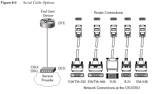
Table 8-8 summarizes the variety of standards that define the types of connectors and physical
signaling protocols used on WAN interfaces.
Frame Relay Protocols
529These cables provide connectivity to the external DSU/CSU, as seen in Figure 8-3. The
interface to the service provider is dependent on the type of connection; the connector could be
RJ-11, RJ-48, RJ-45, or possibly coax.
Some serial interfaces have an integrated DSU/CSU and do not require a cable of the types
shown in the figure. Depending on the expected type of line, a variety of physical interfaces are
used. These interfaces are the same as those used for external CSU/DSU devices.
The TIA is accredited by ANSI for development of telecommunications standards. Also, the
TIA works with the ITU on international standards. For more information on these standards
bodies, and for the opportunity to spend money to get copies of the standards, you can refer to
the Web sites www.tiaonline.org or www.itu.int.
Frame Relay Protocols
Frame Relay provides delivery of variable-sized data frames to multiple WAN-connected sites.
Other than point-to-point links, Frame Relay is the WAN protocol most typically seen by
CCNAs. This section reviews the details of how Frame Relay accomplishes its goal of delivery
of frames to multiple WAN-connected sites.
Frame Relay is a well-chosen name for reminding you that it most closely relates to OSI
Layer 2. The term
frame is generally associated with a collection of data bits that includes anOSI Layer 2 equivalent header. For example, an Ethernet frame includes the Ethernet header/
trailer. Frame Relay uses addresses, but that addressing does not attempt to create a logical
address structure that could be used over a variety of media; therefore, Frame Relay addressing
is closer to OSI Layer 2 addressing standards and is considered to be a Layer 2 protocol. (Refer
to Chapter 3 for a review of OSI layers.)
The remainder of this section summarizes the Frame Relay protocol details expected to be on
the exam.
Table 8-8
WAN Interface StandardsStandard Standards Body
Number of Pins
on Interface
EIA/TIA 232 Telecommunications Industry Association 25
EIA/TIA 449 Telecommunications Industry Association 37
EIA/TIA 530 Telecommunications Industry Association 25
V.35 International Telecommunications Union 34
X.21 International Telecommunications Union 15
530
Chapter 8: WAN Protocols and DesignFrame Relay Features and Terminology
Frame Relay is a multiaccess network, which actually means that more than two devices can
attach to the medium. Multiaccess is the first and most obvious difference between Frame Relay
and leased lines. However, leased lines are used as the access link component of Frame Relay
networks. Consider Figure 8-4, which is a valuable resource for reviewing Frame Relay
concepts.
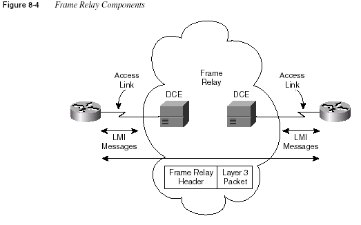
The access link between the router and the Frame Relay switch is a leased line. Both sites
represented in Figure 8-4 are connected to some nearby switch via a leased line. The service
provider interconnects their switches to provide connectivity.
Table 8-9 lists the components in Figure 8-4 and some associated terms.
Table 8-9
Frame Relay Terms and ConceptsVirtual circuit (VC) A VC is a logical concept that represents the path that frames travel
between DTEs. VCs are particularly useful when comparing Frame
Relay to leased physical circuits.
Permanent virtual circuit (PVC) A PVC is a VC that is predefined. A PVC can be equated to a
leased line in concept.
Switched virtual circuit (SVC) An SVC is a VC that is set up dynamically. An SVC can be equated
to a dial connection in concept.
Frame Relay Protocols
531Data terminal equipment (DTE) DTEs are also known as data-circuit termination equipment. For
example, routers are DTEs when connected to a Frame Relay
service from a telecommunication company.
Data communications equipment
(DCE)
Frame Relay switches are DCE devices.
Access link The access link is the leased line between DTE and DCE.
Access rate (AR) The access rate is the speed at which the access link is clocked.
This choice affects the price of the connection.
Committed information rate
(CIR)
The CIR is the rate at which the DTE can send data for an
individual VC, for which the provider commits to deliver that
amount of data. The provider will send any data in excess of this
rate for this VC if its network has capacity at the time. This choice
typically affects the price of each VC.
Burst rate The burst rate is the rate and length of time for which, for a
particular VC, the DTE can send faster than the CIR, and the
provider agrees to forward the data. This choice typically affects
the price of each VC.
Data link connection identifier
(DLCI)
A DLCI is a Frame Relay address and is used in Frame Relay
headers to identify the virtual circuit.
Forward explicit congestion
notification (FECN)
The FECN is the bit in the Frame Relay header that signals to
anyone receiving the frame (switches and DTEs) that congestion is
occurring in the same direction as the frame. Switches and DTEs
can react by slowing the rate by which data is sent in that direction.
Backward explicit congestion
notification (BECN)
The BECN is the bit in the Frame Relay header that signals to
anyone receiving the frame (switches and DTEs) that congestion is
occurring in the opposite (backward) direction as the frame.
Switches and DTEs can react by slowing the rate by which data is
sent in that direction.
Discard eligibility (DE) The DE is the bit in the Frame Relay header that signals to a switch
to, if frames must be discarded, please choose this frame to discard
instead of another frame without the DE bit set.
Nonbroadcast multiaccess
(NBMA)
NBMA refers to a network in which broadcasts are not supported,
but more than two devices can be connected.
Local Management Interface
(LMI)
LMI is the protocol used between a DCE and DTE to manage the
connection. Signaling messages for SVCs, PVC status messages,
and keepalives are all LMI messages.
Link access procedure—frame
mode bearer services (LAPF)
LAPF is the basic Frame Relay header and trailer; it includes
DLCI, FECN, BECN, and DE bits.
Table 8-9
Frame Relay Terms and Concepts (Continued)532
Chapter 8: WAN Protocols and DesignThe definitions for Frame Relay are contained in documents from the ITU and from ANSI. The
Frame Relay Forum, a vendor consortium, also defines several Frame Relay specifications,
many of which have been added to the standards body’s documents. Table 8-10 lists the most
important of these specifications.
LMI and Encapsulation Types
When first learning about Frame Relay, it’s often easy to confuse the LMI and encapsulation
used with Frame Relay; Cisco expects CCNAs to master the differences. The LMI is a
definition of the messages used between the DTE (for example, a router) and the DCE (for
example, the Frame Relay switch owned by the service provider). The encapsulation defines the
headers used, in addition to the basic Frame Relay header, for transporting the frame from DTE
to DTE. The switch and its connected router care about using the same LMI; the switch does
not care about the encapsulation.
The three LMI protocols available in the IOS are defined by Cisco, the ITU, and ANSI, and each
is slightly different and therefore not compatible with the other two. For instance, the Cisco and
ANSI Q.933-A LMIs call for use of DLCI 1023 for LMI messages, whereas T1.617-D calls for
DLCI 0. Some of the messages have different fields in their information elements. The DTE
simply needs to know which of the two (DLCI 1023 or DLCI 0) to use; it must match the one
used by the switch.
Using the same LMI type on a DTE and its connected DCE is required. LMI autosense is
supported by the IOS in version 11.2, so there is no need to code the LMI type. If desired, the
LMI type can be configured, but this disables the autosense feature. One LMI type exists per
serial interface because the LMI controls the single physical access link, which is connected to
a single switch.
The most important LMI message relating to topics on the exam is the LMI
status enquirymessage, which signals whether a PVC is up or down. Even though each PVC is predefined, its
status can change. As with all LMI messages, status enquiry messages flow between the switch
(DCE) and the DTE. For instance, a routing protocol reacts when a PVC is down, signaling that
routes over that PVC are lost.
Table 8-10
Frame Relay Protocol SpecificationsWhat the Specification Defines ITU Document ANSI Document
Data link specifications, including
LAPF header/trailer
Q.922 Annex A T1.618
PVC management, LMI Q.933 Annex A T1.617 Annex D
SVC signaling Q.933 T1.617
Multiprotocol encapsulation
(originated in RFC 1490/2427)
Q.933 Annex E T1.617 Annex F
Frame Relay Protocols
533Table 8-11 outlines the three LMI types, their origin, and the keyword used in the Cisco
framerelaylmi-type
interface subcommand.As with other data link protocols, Frame Relay defines a header and a trailer, with fields in each
that allow the switches and DTEs to successfully deliver the frame across the network.
Encapsulation refers to the process of using such headers and trailers to contain data supplied
by a higher layer. (Refer to Chapter 3 for additional concepts about encapsulation.)
Frame Relay uses a link access procedure—frame bearer services (LAPF) header, defined by
Q.922-A. The sparse LAPF framing provides error detection with an FCS in the trailer, as well
as the DLCI, DE, FECN, and BECN fields. Figure 8-5 diagrams the frame.
Table 8-11
Frame Relay LMI TypesName Document IOS LMI-Type Parameter
Cisco Proprietary cisco
ANSI T1.617 Annex D ansi
ITU Q.933 Annex A q933a

field in the header must define the type of header that begins the Information field. If Frame
Relay is using only the LAPF header, then DTEs (including routers) cannot support multiprotocol
traffic because there is no way to identify the type of protocol in the Information field.
(For more information about the concept of a Protocol Type field in data link headers, refer to
Chapter 3.)
Two solutions were created to compensate for the lack of a Protocol Type field. Cisco and three
other companies created an additional header, which comes first in the Information field shown
in Figure 8-5. It includes a 2-byte-long Protocol Type field, with values matching the same field
used for HDLC by Cisco. The second solution was defined in RFC 1490, “Multiprotocol
Interconnect over Frame Relay,” which was written to ensure multivendor interoperability
between Frame Relay DTEs. This solution includes use of a Protocol Type field and adds many
options, including support for bridged frames. ITU and ANSI later incorporated RFC 1490
headers into specs Q.933 Annex E and T.617 Annex F, respectively.
534
Chapter 8: WAN Protocols and DesignNOTE
RFC 1490 has been superceded by RFC 2427. You probably will want to remember bothnumbers, particularly the older 1490 because it is referred to often in documentation from Cisco
and other vendors.
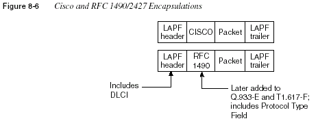
Figure 8-6 provides a conceptual diagram of the two forms of encapsulation.
Because theframes flow from DTE to DTE, both DTEs must agree to the encapsulation used
. However, eachVC can use a different encapsulation.
DLCI Addressing and Frame Relay Switching
The data link connection identifier (DLCI) is the Frame Relay address. DLCIs, not DTEs, are
used to address virtual circuits. The logic and use of these addresses is very different from the
addresses seen for other protocols covered in this book. This difference is mainly due to the use
of the DLCI and the fact that
there is a single DLCI field in the header—there is not a sourceand destination DLCI.
DLCIs are used to address the virtual circuit (VC); the logic behind the way routers use DLCI
values is subtle. For example, in Figure 8-7, Router A has a VC to both Router B and Router C;
Router A will need to use a different DLCI for each VC. The Frame Relay switches swap the
DLCI in transit. For example, Router A sends a frame with DLCI 41, expecting that it will be
delivered to Router B. Likewise, Router A sends frames with DLCI 42 when it wants the frame
to be delivered to Router C.
Frame Relay Protocols
535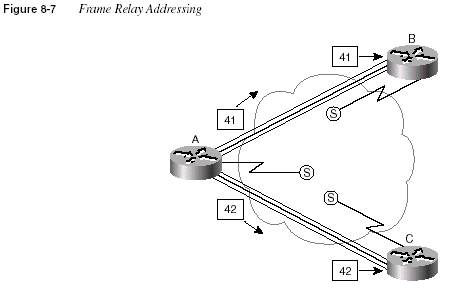
Frame Relay DLCIs are locally significant; this means that the addresses need to be unique only
on the local access link. A popular analogy that explains local addressing is that there can be
only a single street address of 2000 Pennsylvania Avenue, Washington, D.C., but there can be
a 2000 Pennsylvania Avenue in every town in the United States. Likewise, DLCIs must be
unique on each access link.
In Figure 8-7, as frames traverse Router A’s access link, they have either DLCI 41 or 42 in the
header, which meets the requirement that the addresses be unique on that access link. Likewise,
for all VCs terminating at Router B, unique DLCI values must be used for each one. Because
there is only one VC to Router B in Figure 8-7, there is no possibility of an overlap.
DLCIs are usually changed as the frames traverse the Frame Relay network. Consider the
revised network of Figure 8-8, in which DLCI 41 and 42 are still used by Router A on the access
link. Before the frames are forwarded on the access links to Router B and Router C, the Frame
Relay switches convert the DLCI to a value of 40 in each case. The DLCI values are chosen by
the service provider; the only requirement of local addressing can be summarized as follows:
DLCIs must be unique on each access link. The DLCI used to identify an individual
VC on one access link has no bearing on the value that is chosen to identify the VC
on the access link at the other end of the VC.
536
Chapter 8: WAN Protocols and Design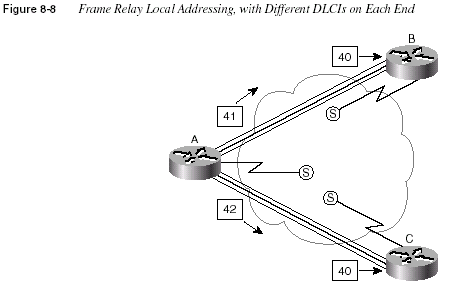
With the convention shown in Figure 8-8, the DLCI values are different on each end of the VC.
However, the values shown in Figure 8-7 are also valid. In practice, the style shown in Figure
8-8 is the typical choice, but it seems to be a bit more confusing. But why? The answer lies in
a term called
global addressingThe concept of global addressing is the reason that typical Frame Relay networks use a different
DLCI value on each end of the VC. Global addressing allows you to think of the Frame Relay
network like a LAN in terms of addressing concepts. Consider Figure 8-9, with the DLCI values
shown. In this figure, think of the DLCI values as an address for the DTE, which is similar to
how a unicast MAC address represents a LAN card.
On a LAN, if Host B wants to send a frame to Host A, Host B sends a frame with Host A’s MAC
address as the destination. Similarly, if Router B wants to send a frame to Router A, then Router
B (by the convention of global addressing) sends a frame with Router A’s global DLCI value in
the header. Likewise, Router C sends frames with DLCI 40 to reach Router A, by convention.
Router A sends frames with DLCI 41 to reach Router B, and with DLCI 42 to reach Router C,
again, by the convention of global addressing. Figure 8-9 shows the DLCIs used for global
addressing and the actual values placed into the Frame Relay headers for correct delivery across
the network. Table 8-12 summarizes the DLCIs used in the figure.
Frame Relay Protocols
537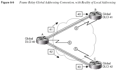
Figure 8-9 shows a frame being sent from Router A to Router B in one case, and to Router C in
the other case. As Router A sends a frame with DLCI 41, the Frame Relay switches send the
frame toward Router B. Before being sent on the access link to Router B, the final switch
changes the DLCI to 40 so that Router B knows who sent the frame. Similarly, Router A sends
a frame with DLCI 42, and it is received by Router C with DLCI 40.
In fact, the DLCIs used match the sample network with local addressing of Figure 8-8. In
essence:
•
Local addressing is how Frame Relay addressing works. However, by following theconvention of global addressing, planning is easier because the addressing appears similar
to LAN addressing.
•
A global address for one DTE simply means that all other DTEs with a VC to this oneDTE use its global address on their local access links.
Table 8-12
DLCI Swapping in Frame Relay CloudFrame Sent by
Router . . . With DLCI Field
Is Delivered to
Router . . . With DLCI Field
A 41 B 40
A 42 C 40
B 40 A 41
C 40 A 42
538
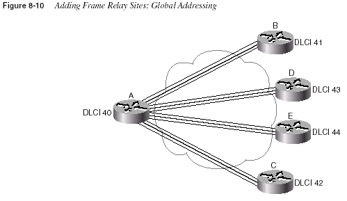
Chapter 8: WAN Protocols and DesignOne particularly convenient benefit of global addressing is that new sites can be added with
more convenience. Examine Figure 8-10, with Routers D and E added. The service provider
simply states that global DLCI 43 and 44 will be used for these two routers. If these two routers
also have only one PVC to Router A, all the DLCI planning is complete. You know that Router
D and Router E will use DLCI 40 to reach Router A, and that Router A will use DLCI 43 to
reach Router D and DLCI 44 to reach Router E.
The remaining samples in this chapter use global addressing in any planning diagrams, unless
otherwise stated. One practical way to determine whether the diagram lists the local DLCIs or
the global DLCI convention is this: If two VCs terminate at a DTE and a single DLCI is shown,
then it probably represents the global DLCI convention. If one DLCI is shown per VC, then it
is depicting local DLCI addressing.
Network Layer Concerns with Frame Relay
As a CCNA, you will need to concern yourself with three key issues relating to Layer 3 flows
over Frame Relay:
•
Choices for Layer 3 addresses on Frame Relay interfaces•
Broadcast handling•
Split horizonThe sections that follow cover these issues in depth.
Frame Relay Protocols
539Layer 3 Addressing
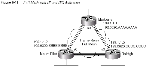
This section examines three cases of Layer 3 addressing when using Frame Relay. Figure 8-11
starts the first case with an illustration of a fully meshed Frame Relay network. In a full mesh,
each router has a direct connection to every other router, allowing the Frame Relay cloud to be
treated as one Layer 3 network. Figure 8-11 also shows IPX and IP addresses. The IPX and IP
addresses would be configured as subcommands on the serial interface. Table 8-13 summarizes
the addresses used in Figure 8-11.
The second case is a partially meshed Frame Relay network (see Figure 8-12). Because all four
routers do not have VCs to each other, each VC uses a different set of Layer 3 groups. Table
8-14 shows the IPX and IP addresses for the partially meshed Frame Relay network illustrated
in Figure 8-12. The addresses would be configured as subcommands on the serial interface.
(
Note: The notation /24 signifies a subnet mask with 24 binary 1s—in other words,255.255.255.0.)
Table 8-13
IP and IPX Addresses, with No SubinterfacesRouter
IP Address of
Frame Relay
Interface
IPX Network of
Frame Relay
Interface IPX Address
Mayberry 199.1.1.1 199 199.0200.aaaa.aaaa
Mount Pilot 199.1.1.2 199 199.0200.bbbb.bbbb
Raleigh 199.1.1.3 199 199.0200.cccc.cccc
540
Chapter 8: WAN Protocols and Design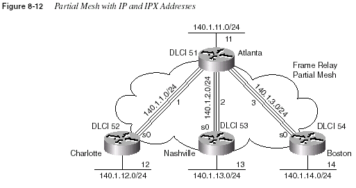
Subinterfaces allow the Atlanta router to have three IP addresses and three IPX addresses
associated with its serial 0 interface. Subinterfaces can treat each VC as though it were a pointto-
point serial link. Each of the three subinterfaces of serial 0 on Atlanta would be assigned a
different IP address and IPX address from the list in Table 8-14. Example configurations follow
in the next section of this chapter.
The third case of Layer 3 addressing is a hybrid between the first two illustrated in Figure 8-11
and Figure 8-12. Consider Figure 8-13, which shows a trio of routers with VCs between each
of them, as well as two other VCs to remote sites.
Table 8-14
IP and IPX Addresses, with Point-to-Point SubinterfacesRouter Subnet IP Address IPX Network IPX Address
Atlanta 140.1.1.0/24 140.1.1.1 1 1.0200.aaaa.aaaa
Charlotte 140.1.1.0/24 140.1.1.2 1 1.0200.bbbb.bbbb
Atlanta 140.1.2.0/24 140.1.2.1 2 2.0200.aaaa.aaaa
Nashville 140.1.2.0/24 140.1.2.3 2 2.0200.cccc.cccc
Atlanta 140.1.3.0/24 140.1.3.1 3 3.0200.aaaa.aaaa
Boston 140.1.3.0/24 140.1.3.4 3 3.0200.dddd.dddd
Frame Relay Protocols
541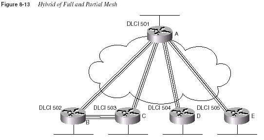
Two options exist for Layer 3 addressing in this case. The first is to treat each VC as a separate
Layer 3 group; five subnets and five IPX networks would be needed for the Frame Relay
network. However, if Routers A, B, and C are considered alone, they meet the criteria that each
can send packets directly to each other, like a full mesh. This would allow Routers A, B, and C
to use one subnet and IPX network. The other two VCs—between A and D, and between A and
E—are treated as two separate Layer 3 groups. The result is a total of three subnets and three
IPX network numbers.
To accomplish either style of Layer 3 addressing in this third and final case, subinterfaces are
used. Point-to-point subinterfaces are used when a single VC is considered to be all that is in
the group. Multipoint subinterfaces are used among Routers A, B, and C in Figure 8-13. The
section “Frame Relay Configuration,” later in the chapter, provides full configurations for all
three cases illustrated in Figure 8-11, Figure 8-12, and Figure 8-13. Table 8-15 summarizes the
addresses and subinterfaces used.
Table 8-15
IP and IPX Addresses, and Point-to-Point and Multipoint SubinterfacesRouter Subnet IP Address
IPX
Network IPX Address
Subinterface
Type
A 140.1.1.0/24 140.1.1.1 1 1.0200.aaaa.aaaa Multipoint
B 140.1.1.0/24 140.1.1.2 1 1.0200.bbbb.bbbb Multipoint
C 140.1.1.0/24 140.1.1.3 1 1.0200.cccc.cccc Multipoint
A 140.1.2.0/24 140.1.2.1 2 2.0200.aaaa.aaaa Point-to-point
D 140.1.2.0/24 140.1.2.4 2 2.0200.dddd.dddd Point-to-point
A 140.1.3.0/24 140.1.3.1 3 3.0200.aaaa.aaaa Point-to-point
E 140.1.3.0/24 140.1.3.5 3 3.0200.eeee.eeee Point-to-point
542
Chapter 8: WAN Protocols and DesignBroadcast Handling
Broadcasts are not supported over a Frame Relay network. In other words, no capability exists
for a DTE to send a frame that is replicated and delivered across more than one VC. However,
routers need to send broadcasts for several features to work. In particular, routing protocol
updates and SAP updates are broadcasts.
The solution to the broadcast dilemma for Frame Relay has two parts. First, the IOS sends
copies of the broadcasts across each VC that you instruct it to. Of course, if there are only a few
VCs, this is not a big problem. However, if hundreds of VCs terminate in one router, then for
each broadcast, hundreds of copies could be sent. The IOS can be configured to limit the
amount of bandwidth that is used for these replicated broadcasts.
As the second part of the solution, the router tries to minimize the impact of the first part of the
solution. The router places these broadcasts into a different queue than user traffic so that the
user does not experience a large spike in delay each time some broadcast is replicated and sent
over each VC.
NOTE
Although the CCNP exam, not the CCNA exam, covers such issues about dealing withoverhead, a short example can show the significance of this overhead. For example, if a router
knows 1000 routes, uses RIP, and has 50 VCs, then 1.072MB of RIP updates are sent every 30
seconds. That averages to 285kbps. (Math: 536-byte RIP packets, with 25 routes in each packet,
for 40 packets per update, with copies sent over 50 VCs: 536
× 40 × 50 = 1.072 megabytes perupdate interval. 1.072
× 8 / 30 seconds = 285kbps).Knowing how to tell the router to forward these broadcasts out to each VC will be important on
the CCNA exam and is covered in the “Frame Relay Configuration” section later in this chapter.
The issues that relate to dealing with the volume of these updates is more likely a topic for the
CCNP and CCIE exams.
Split Horizon
Split horizon is useful for preventing routing loops by preventing a router from advertising a
route onto the same interface in which the route was learned. (Refer to Chapter 6, “Routing
Protocols,” for a full explanation.) However, split horizon could cause some problems with
Frame Relay. Thankfully, several configuration options help you deal with this issue. But first,
refer back to Figure 8-12. If split horizon was enabled on Atlanta, then Atlanta would learn
about 140.1.12.0/24 from Charlotte but would not advertise the route to 140.1.12.0/24 in its
updates to Nashville or Boston.
Split horizon logic applies to subinterfaces if they are configured. In other words, Atlanta uses
a different subinterface for each VC to the three remote sites. Split horizon is enabled on each
Frame Relay Protocols
543subinterface. However, because the routing updates from Charlotte are considered to enter
Atlanta via one subinterface, and because routing updates to Nashville and Boston exit two
other subinterfaces, then advertising 140.1.12.0/24 to Nashville and Boston is allowed.
Split horizon would be a problem in Figure 8-11, however. When all three VCs are up, no
problem exists. However, if the VC from Mount Pilot to Raleigh went down, then split horizon
on Mayberry would be harmful. Mount Pilot will advertise routes to 199.1.11.0, and Mayberry
will receive that information in a routing update. However, because no subinterfaces are used,
Mayberry would not advertise 199.1.11.0 to Raleigh with split horizon enabled.
The multipoint subinterfaces in Figure 8-13 would experience the same problems for the same
reasons described for Figure 8-11.
The solution to the problem is to disable split horizon when not using subinterfaces or when
using multipoint subinterfaces. The IOS defaults to disable split horizon on Frame Relay
interfaces in all cases except for point-to-point subinterfaces. Table 8-16 summarizes these
settings and shows that the current default settings work around the split horizon issues
described in the last few paragraphs.
If the default value for split horizon is not desired, then the
ip split horizon interfaceconfiguration command can be used to enable split horizon. Similarly, the
no ip split horizoninterface configuration command disables split horizon on that interface.
How Address Mapping Works
Frame Relay mapping is a topic you could ignore and still make Frame Relay work in a Cisco
router. However, Cisco requires that CCNAs understand Frame Relay address mapping, for two
main reasons. First, static mapping is just the kind of nasty question that is likely to crop up on
the exam. Second, understanding mapping offers a good opportunity to review the concepts
behind routing. As with most features implemented dynamically and by default, you can ignore
mapping most of the time.
Mapping is required when using some other data links, but not all. For example, with IP, the
ARP process dynamically builds a mapping between an IP address and a LAN address. This
section discusses the basics behind why mapping is needed for LAN connections and Frame
Relay, with a focus on Frame Relay.
Consider Figure 8-14 and the routing table that follows (Table 8-17).
Table 8-16
Split Horizon and Frame Relay InterfacesType of Configuration Split Horizon Is . . .
No subinterfaces Disabled
Point-to-point subinterfaces Enabled
Multipoint subinterfaces Disabled
544
Chapter 8: WAN Protocols and Design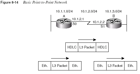
The core routing logic must be considered to fully appreciate mapping. Router A receives an
Ethernet frame from some host and strips the Ethernet header (and trailer). The destination IP
address of the packet is compared to the IP routing table, and an entry is matched. The matched
routing table entry tells the router to route the packet out serial 0 to 10.1.2.2 next (Router B’s
S1 IP address). Router A builds the HDLC header/trailer and sends the frame.
The fact that Router B’s IP address on the common serial link is 10.1.2.2 has nothing to do with
the contents of the HDLC header and trailer; Router B’s IP address is immaterial in this case.
If Router A can get the frame across the link, there is only one possible recipient—Router B.
So, no mapping is needed between the Layer 3 address and the HDLC address on a point-topoint
link.
Now consider a diagram with Ethernet between the routers (see Figure 8-15) and the routing
table that follows (see Table 8-18).
Table 8-17
Partial Routing Table on Router A for Figure 8-14Subnet Outgoing Interface Next Router
10.1.3.0 serial 0 10.1.2.2
Frame Relay Protocols
545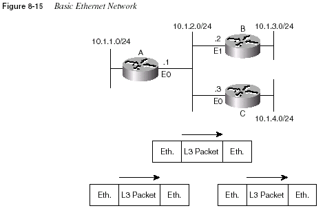
Again consider the core routing logic. Router A receives an Ethernet frame from some host and
strips the Ethernet header (and trailer). Router A decides to route the packet out Ethernet 0 to
the next router, 10.1.2.2 (Router B’s E1 IP address). Router A builds the new Ethernet header/
trailer and sends the frame.
Router A builds the Ethernet header based on the next-hop router’s IP address—namely,
10.1.2.2 (Router B’s E1 IP address). The destination Ethernet address in the header built by
Router A is Router B’s E1 address. Router A learns this information dynamically using the
IP ARP protocol. Similarly, with IPX routing, the next-hop router’s IPX address has the
corresponding LAN address embedded in the IPX address. (With other Layer 3 protocols, there
are other processes on LANs for learning the corresponding LAN address.) The information
learned by IP ARP in this case is the information that maps the next-hop IP address to the LAN
address used to reach it; this is called
mapping. A more general definition for mapping follows:The information that correlates to the next-hop router’s Layer 3 address, and the
Layer 2 address used to reach it, is called mapping. Mapping is needed on
multiaccess networks.
Table 8-18
Partial Routing Table on Router A for Figure 8-15Subnet Outgoing Interface Next Router
10.1.3.0 Ethernet 0 10.1.2.2
546
Chapter 8: WAN Protocols and DesignNow consider the Frame Relay network in Figure 8-16, along with the routing table in
Table 8-19.
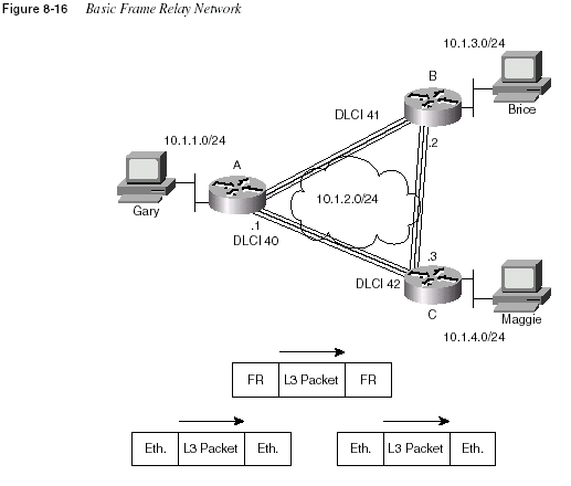
Again consider the core routing logic. Router A receives an Ethernet frame from some host and
strips the Ethernet header (and trailer). It decides to route the packet out serial 0 to the next
router, 10.1.2.2 (Router B’s S0 IP address). Router A builds the Frame Relay header/trailer and
sends the frame.
Although Router A knows the serial interfaces out which to forward the frame, Router A does
not know the correct DLCI yet. A mapping is needed in Router A to correlate 10.1.2.2 (Router
B) and the DLCI Router A used to reach Router B. However, the same IP ARP used on LANs
Table 8-19
Partial Routing Table on Router A for Figure 8-16Subnet Outgoing Interface Next Router
10.1.3.0 Serial 0 10.1.2.2
Frame Relay Protocols
547will not work on Frame Relay because there is no support for broadcasts. Therefore, ARP
cannot be used to discover that DLCI.
Two solutions exist by which Router A can learn the mapping between Router B’s IP address
and DLCI. One uses a statically configured mapping, and the other uses a dynamic process
called
Inverse ARP.Table 8-20 lists the IP and IPX addresses of the three routers in Figure 8-16.
Example 8-3 lists the static Frame Relay map for the three routers in Figure 8-16. The DLCIs
in Table 8-20 are the same as those used in Figure 8-16.
Consider the case in which Gary makes an FTP connection to Brice. The
frame-relay mapcommand for Router A referencing 10.1.2.2 would be used for packets originating from Gary
and going to Brice. Conversely, a packet sent back from Brice to Gary would cause Router B
to use its map statement referring to Router A’s IP address of 10.1.2.1. Mapping is needed for
Table 8-20
Layer 3 Addresses and DLCIs Used with Figure 8-16Router Global DLCI IP Address IPX Address
A 40 10.1.2.1 2.0200.aaaa.aaaa
B 41 10.1.2.2 2.0200.bbbb.bbbb
C 42 10.1.2.3 2.0200.cccc.cccc
Example 8-3
frame-relay map CommandsRouter A:
interface serial 0
frame-relay map ip 10.1.2.2 41 broadcast
frame-relay map ipx 2.0200.bbbb.bbbb 41 broadcast
frame-relay map ip 10.1.2.3 42 broadcast
frame-relay map ipx 2.0200.cccc.cccc 42 broadcast
Router B:
interface serial 0
frame-relay map ip 10.1.2.1 40 broadcast
frame-relay map ipx 2.0200.aaaa.aaaa 40 broadcast
frame-relay map ip 10.1.2.3 42 broadcast
frame-relay map ipx 2.0200.cccc.cccc 42 broadcast
Router C:
interface serial 0
frame-relay map ip 10.1.2.1 40 broadcast
frame-relay map ipx 2.0200.aaaa.aaaa 40 broadcast
frame-relay map ip 10.1.2.2 41 broadcast
frame-relay map ipx 2.0200.bbbb.bbbb 41 broadcast
548
Chapter 8: WAN Protocols and Designeach next-hop Layer 3 address for each Layer 3 protocol being routed. Even with a network this
small, the configuration process can be laborious. A better solution is a dynamic protocol called
Inverse ARP.
Inverse ARP acquires mapping information in a manner opposite of IP ARP, but the information
that maps the Layer 3 and Layer 2 addresses is still found. Inverse ARP is basic; after the VC
is up, each DTE announces its network layer address to the DTE on the other end of the VC.
(Inverse ARP is enabled by default at IOS 11.2 and beyond, unless point-to-point subinterfaces
are used.) Table 8-21 summarizes what would occur in the network in Figure 8-16.
Although Table 8-21 lists a seemingly large number of messages, no static
frame-relay mapcommands are needed. All the necessary mapping information is learned dynamically.
Inverse ARP is enabled by default if no subinterfaces are in use. Inverse ARP is also on by
default for multipoint subinterfaces. However, Inverse ARP is not enabled on point-to-point
subinterfaces because point-to-point subinterfaces behave like a true point-to-point line in
regard to routing; if the packet needs to be sent out a point-to-point subinterface, then there is
only one possible next router and only one DLCI in use. So, Inverse ARP is not needed with
point-to-point subinterfaces.
Table 8-21
Inverse ARP Messages for Figure 8-16Sending
Router
DLCI in
Header of
I-ARP Frame
When Sent
Receiving
Router
DLCI in
Header of
I-ARP Frame
When
Received
Information in
Inverse ARP
A 41 B 40 I am 10.1.2.1.
A 41 B 40 I am 2.0200.aaaa.aaaa.
A 42 C 40 I am 10.1.2.1.
A 42 C 40 I am 2.0200.aaaa.aaaa.
B 40 A 41 I am 10.1.2.2.
B 40 A 41 I am 2.0200.bbbb.bbbb.
B 42 C 41 I am 10.1.2.2.
B 42 C 41 I am 2.0200.bbbb.bbbb.
C 40 A 42 I am 10.1.2.3.
C 40 A 42 I am 2.0200.cccc.cccc.
C 41 B 42 I am 10.1.2.3.
C 41 B 42 I am 2.0200.cccc.cccc.
Frame Relay Protocols
549Review: Basic Frame Relay Initialization
Now that the text has covered all the pertinent concepts, it’s time to review the basic
initialization process on a Frame Relay network. First, the LMI sends a status enquiry notifying
the DTE when the VC is up. After this process, Inverse ARP frames are sent by the routers in
each direction for each Layer 3 protocol configured for the VC. Packets can be forwarded at this
point. Of course, routing protocols will send their initial updates, routes will be learned, and
only then will end-user traffic be able to flow. Figure 8-17 outlines the process.
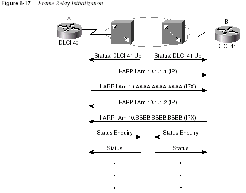
LMI status messages inform the routers when the PVC first comes up. Because Inverse ARP
frames could not be delivered until the VC was up but can be delivered now, the Inverse ARP
announcements declare the Layer 3 addresses. Unless keepalives have been turned off, both the
switch and the router expect to send and receive periodic status and status enquiry messages,
respectively.
Compression
Compression can be performed on frames sent out a Frame Relay interface. Two general types
of compression are allowed: payload compression and TCP header compression. With TCP
550
Chapter 8: WAN Protocols and Designheader compression, only the TCP header is compressed; all other headers and data remain
uncompressed. As its name suggests, payload compression compresses the payload of the
Frame Relay frame.
Regardless of which type of compression is used, the Frame Relay header itself cannot be
compressed. If the Frame Relay header were compressed, the intermediate Frame Relay
switches would not be capable of forwarding the frames.
Payload Compression
Figure 8-18 provides the basic concept behind payload compression and shows what is
compressed:
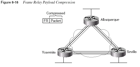
If payload compression was used on the VC between Albuquerque and Yosemite, the Frame
Relay header would remain intact, but the packet (the payload) would be compressed before
transmission and uncompressed upon reception.
Two types of payload compression are available. The first historically used the STAC algorithm,
which predicts the values that follow the earlier bytes in the compressed payload. The algorithm
did not follow any standard. That process works fine, but it can run only in software—no
support for this algorithm exists for Frame Relay on the Versatile Interface Processor (VIP) or
the Compression Service Adapter (CSA).
The second payload compression option is to use the Frame Relay Forum standard compression.
The FRF.9 Implementation Agreement (IA) defines the details and is available free
from the Frame Relay Forum if you would like to see more details (http://www.frforum.com).
The FRF.9 document calls for the use of the STAC algorithm as well, but with some details that
differ from the original Cisco protocol. Cisco has added support for the FRF.9 payload
compression into the CSA and the VIP2. Even if compressing in software, Cisco recommends
using the FRF.9 payload compression over the original Cisco implementation of STAC.
Frame Relay Configuration
551TCP Header Compression
TCP header compression is seemingly unnecessary, given that payload compression is
available. Why bother just compressing the TCP header? Well, compression algorithms can be
optimized if the data to be compressed has a known format and a tendency toward using
particular values. The 40-byte TCP header can be reduced to an average of 10 bytes. One of the
biggest reasons that TCP header compression can be beneficial is that it takes little processing
because of the efficient compression algorithm. Also, if a large amount of traffic is made up of
small IP packets with TCP, then the compression ratio can be more than 2-to-1. For instance, in
the “old” days when Telnet was used on a frequent basis by end users, many IP packets were
sent with the IP header, the TCP header, and just a few bytes of data typed by the user. So,
efficient compression with the possibility of more than 2-to-1 compression ratio is a very
reasonable option. If most of the IP packets using TCP in a network are large, then the
compression ratio will not be very high, making TCP header compression a less-attractive
option.
Frame Relay Configuration
Configuration of Frame Relay in a Cisco router is relatively straightforward if all the defaults
are taken. Cisco expects CCNAs to know several of the optional parameters that are shown in
this section as well.
Hands-on experience is the best way to fully learn the details of configuration. In lieu of that,
this section lists commands, provides examples, and points out tricky features. Table 8-22 and
Table 8-23 summarize the more popular commands used for Frame Relay configuration and
verification. Two configuration samples follow. The Cisco IOS documentation is an excellent
reference for additional IP commands, and the Cisco Press book
Interconnecting Cisco NetworkDevices
is an excellent reference, particularly if you are not able to attend the instructor-ledversion of the class.
Table 8-22
Frame Relay Configuration CommandsCommand Configuration Mode Purpose
encapsulation frame-relay
[
ietf | cisco]Interface Defines Frame Relay
encapsulation that is used rather
than HDLC, PPP, and so on.
frame-relay lmi-type
{ansi |q933a
| cisco}Interface Defines the type of LMI
messages sent to the switch.
bandwidth
num Interface Sets the route’s perceived speedof the interface. Bandwidth is
used by some routing protocols
to influence the metric.
continues
552
Chapter 8: WAN Protocols and DesignDetermining when and how to use subinterfaces for Frame Relay configuration is the most
difficult part of the configuration. Subinterfaces are never required; subinterfaces can be used
in any Frame Relay configuration, and most sites tend to use them. Some general guidelines
when using subinterfaces include the following:
•
When the network is partially meshed, using point-to-point subinterfaces overcomes splithorizon issues by treating each subinterface as a separate interface.
•
When the network is partially meshed, using a multipoint subinterface will work.•
When the network is truly fully meshed, a multipoint subinterface can be used to reducethe number of network-layer groups (for example, IP subnets) that are used.
frame-relay map
protocolprotocol-address dlci
[payloadcompress{
packet-by-packet |frf9 stac
}] [broadcast] [ietf |cisco
]Interface Statically defines a mapping
between a network layer address
and a DLCI.
keepalive
sec Interface Defines whether and how oftenLMI status enquiry messages
are sent and expected.
interface serial
num.sub [pointto-point
| multipoint]Global Creates a subinterface, or
references a previously created
subinterface.
frame-relay interface-dlci
dlci[
ietf | cisco]Interface Defines a DLCI used for a VC to
another DTE.
frame-relay payload-compress
{
packet-by-packet | frf9 stac}Interface subcommand Defines payload compression on
point-to-point subinterfaces.
Table 8-23
Frame Relay Related EXEC CommandsCommand Function
show interface
Shows physical interface status.show frame-relay
{pvc | map |lmi
}Shows PVC status, mapping (dynamic and static), and LMI status.
debug frame-relay
{lmi |events
}Lists messages describing LMI flows (LMI option). The
eventsoption lists inverse ARP information. Other options include
lapf,informationelements
, ppp, and packet.Table 8-22
Frame Relay Configuration Commands (Continued)Command Configuration Mode Purpose
Frame Relay Configuration
553•
When the network is truly fully meshed, point-to-point subinterfaces can be used. This istypically chosen to maintain consistency with other Frame Relay networks elsewhere in
the network that are not fully meshed. This choice requires a larger number of IP subnets
to be used.
•
When the network contains some fully meshed portions (for example, when 3 sites haveVCs between each other but the other 10 do not), a multipoint subinterface can be used
for the fully meshed portion and point-to-point subinterfaces can be used for the rest.
•
When the network contains some fully meshed portions (for example, when 3 sites haveVCs between each other but the other 10 do not), using only point-to-point subinterfaces
is another option. This requires more IP subnets and IPX networks than when using a
multipoint subinterface for the fully meshed portion of the network.
•
Many sites avoid confusion by always using point-to-point subinterfaces to maintainconsistency.
Correlating the DLCI(s) to their subinterfaces is required when using either type of
subinterface. LMI enquiry messages notify the router that PVCs are active; the router then
needs to know which subinterface uses the DLCI. An individual DLCI is used by only one
subinterface. For a point-to-point subinterface, only one DLCI is used; for multipoint, many
DLCIs are used.
Three samples of Layer 3 addressing were used earlier in the chapter, with the networks
diagrammed in Figure 8-11, Figure 8-12, and Figure 8-13. The configurations matching those
networks and addresses are shown next.
Configuring Networks Without Subinterfaces
The first sample network (based on the environment depicted in Figure 8-11) does not use
subinterfaces. Example 8-4, Example 8-5, and Example 8-6 show the configuration for this
network.
Example 8-4
Mayberry Configurationipx routing 0200.aaaa.aaaa
!
interface serial0
encapsulation frame-relay
ip address 199.1.1.1 255.255.255.0
ipx network 199
!
interface ethernet 0
ip address 199.1.10.1 255.255.255.0
ipx network 1
!
router igrp 1
network 199.1.1.0
network 199.1.10.0
554
Chapter 8: WAN Protocols and DesignThe configuration is simple in comparison with the protocol concepts. All default settings (IOS
version 12.0) were used and are as follows:
•
The LMI type is automatically sensed.•
The encapsulation is Cisco instead of IETF.•
PVC DLCIs are learned via LMI status messages.•
Inverse ARP is enabled (by default) and is triggered when the status message declaringthat the VCs are up has been received.
In some cases, the default values will not be appropriate. For instance, if one router was not a
Cisco router and did not support Cisco encapsulation, then IETF encapsulation would be
required. For the purpose of showing an alternate configuration, suppose that the following
requirements were added:
•
The Raleigh router requires IETF encapsulation on both VCs.•
Mayberry’s LMI type should be ANSI; LMI autosense should not be used.Example 8-5
Mount Pilot Configurationipx routing 0200.bbbb.bbbb
!
interface serial0
encapsulation frame-relay
ip address 199.1.1.2 255.255.255.0
ipx network 199
!
interface ethernet 0
ip address 199.1.11.2 255.255.255.0
ipx network 2
!
router igrp 1
network 199.1.1.0
network 199.1.11.0
Example 8-6
Raleigh Configurationipx routing 0200.cccc.cccc
!
interface serial0
encapsulation frame-relay
ip address 199.1.1.3 255.255.255.0
ipx network 199
!
interface ethernet 0
ip address 199.1.12.3 255.255.255.0
ipx network 3
!
router igrp 1
network 199.1.1.0
network 199.1.12.0
Frame Relay Configuration
555Example 8-7 and Example 8-8 show the changes that would be made to Mayberry and Raleigh.
The encapsulation was changed in two different ways. Raleigh changed its encapsulation for
both its PVCs with the
ietf keyword on the encapsulation command. Mayberry could notchange because only one of the two VCs to Mayberry was directed to use IETF encapsulation.
So, Mayberry was forced to code the
frame-relay interface-dlci command, coding the DLCIfor the VC to Raleigh. The
ietf keyword was needed to change from the default encapsulationof cisco.
The LMI configuration in Mayberry would have been fine without any changes because
autosense would have recognized ANSI. However, by coding the
frame-relay lmi-type ansi,Mayberry is forced to use ANSI because this command disables autonegotiation of the LMI
type.
Mount Pilot’s
frame-relay interface-dlci configuration would need to be modified likeMayberry’s for the VC from Mount Pilot to Raleigh so that VC will use IETF encapsulation.
This change is not shown in an example.
Configuring Networks with Point-to-Point Subinterfaces
The second sample network (based on the environment depicted in Figure 8-12) uses point-topoint
subinterfaces. Example 8-9, Example 8-10, Example 8-11, and Example 8-12 show the
configuration for this network.
Example 8-7
Mayberry Configuration with New Requirementsipx routing 0200.aaaa.aaaa
!
interface serial0
encapsulation frame-relay
frame-relay lmi-type ansi
frame-relay interface-dlci 42 ietf
ip address 199.1.1.1 255.255.255.0
ipx network 199
! rest of configuration unchanged from Example 8-4.
Example 8-8
Raleigh Configuration with New Requirementsipx routing 0200.cccc.cccc
!
interface serial0
encapsulation frame-relay ietf
ip address 199.1.1.3 255.255.255.0
ipx network 199
!
! rest of configuration unchanged from example 8-6.
556
Chapter 8: WAN Protocols and DesignExample 8-9
Atlanta Configurationipx routing 0200.aaaa.aaaa
!
interface serial0
encapsulation frame-relay
!
interface serial 0.1 point-to-point
ip address 140.1.1.1 255.255.255.0
ipx network 1
frame-relay interface-dlci 52
!
interface serial 0.2 point-to-point
ip address 140.1.2.1 255.255.255.0
ipx network 2
frame-relay interface-dlci 53
!
interface serial 0.3 point-to-point
ip address 140.1.3.1 255.255.255.0
ipx network 3
frame-relay interface-dlci 54
!
interface ethernet 0
ip address 140.1.11.1 255.255.255.0
ipx network 11
Example 8-10
Charlotte Configurationipx routing 0200.bbbb.bbbb
!
interface serial0
encapsulation frame-relay
!
interface serial 0.1 point-to-point
ip address 140.1.1.2 255.255.255.0
ipx network 1
frame-relay interface-dlci 51
!
interface ethernet 0
ip address 140.1.12.2 255.255.255.0
ipx network 12
Example 8-11
Nashville Configurationipx routing 0200.cccc.cccc
!
interface serial0
encapsulation frame-relay
!
interface serial 0.2 point-to-point
ip address 140.1.2.3 255.255.255.0
ipx network 2
frame-relay interface-dlci 51
!
Frame Relay Configuration
557Point-to-point subinterfaces were used in this configuration because the network is not fully
meshed. The
frame-relay interface-dlci command is needed when using subinterfaces. This isbecause the status messages come into the physical interface stating that a VC with a particular
DLCI is up; the IOS then needs to associate that VC with a subinterface.
The subinterface numbers in the example configuration happen to match on either end of the
VCs. For example, subinterface 2 was used in Atlanta for the PVC to Nashville; Nashville also
uses subinterface 2. There is no requirement that the subinterface numbers be the same.
Example 8-13 shows the output from the most popular IOS Frame Relay EXEC commands for
monitoring Frame Relay, as issued on router Atlanta.
interface ethernet 0
ip address 140.1.13.3 255.255.255.0
ipx network 13
Example 8-12
Boston Configurationipx routing 0200.dddd.dddd
!
interface serial0
encapsulation frame-relay
!
interface serial 0.3 point-to-point
ip address 140.1.3.4 255.255.255.0
ipx network 3
frame-relay interface-dlci 51
!
interface ethernet 0
ip address 140.1.14.4 255.255.255.0
ipx network 14
Example 8-13
Output from EXEC Commands on AtlantaAtlanta#
show frame-relay pvcPVC Statistics for interface Serial0 (Frame Relay DTE)
DLCI = 52, DLCI USAGE = LOCAL, PVC STATUS = ACTIVE, INTERFACE = Serial0.1
input pkts 843 output pkts 876 in bytes 122723
out bytes 134431 dropped pkts 0 in FECN pkts 0
in BECN pkts 0 out FECN pkts 0 out BECN pkts 0
in DE pkts 0 out DE pkts 0
out bcast pkts 876 out bcast bytes 134431
pvc create time 05:20:10, last time pvc status changed 05:19:31
--More--
DLCI = 53, DLCI USAGE = LOCAL, PVC STATUS = ACTIVE, INTERFACE = Serial0.2
input pkts 0 output pkts 875 in bytes 0
out bytes 142417 dropped pkts 0 in FECN pkts 0
Example 8-11
Nashville Configuration (Continued)continues
558
Chapter 8: WAN Protocols and DesignUseful management information is held in the output of the
show frame-relay pvc command.The counters for each VC, including increments in the FECN and BECN counters, can be
particularly useful. Likewise, comparing the packets/bytes sent versus what is received on the
other end of the VC is also quite useful because it reflects the number of packets/bytes lost
inside the Frame Relay cloud. Also, seeing a PVC as active means that it is usable (as opposed
to inactive), which is a great place to start when troubleshooting. All this information can be
better gathered by an SNMP manager.
The output of the
show frame-relay map command is surprising after the discourse aboutmapping. A DLCI is listed in each entry, but no mention of corresponding Layer 3 addresses
is made. However, because the subinterfaces are point-to-point, this omission by IOS is
intended—the subinterface acts like a point-to-point link, with two participants. Mapping is
needed only when more than two devices are attached to the link. (See the section “How
Address Mapping Works,” earlier in this chapter, for more information.)
in BECN pkts 0 out FECN pkts 0 out BECN pkts 0
in DE pkts 0 out DE pkts 0
out bcast pkts 875 out bcast bytes 142417
pvc create time 05:19:51, last time pvc status changed 04:55:41
--More--
DLCI = 54, DLCI USAGE = LOCAL, PVC STATUS = ACTIVE, INTERFACE = Serial0.3
input pkts 10 output pkts 877 in bytes 1274
out bytes 142069 dropped pkts 0 in FECN pkts 0
in BECN pkts 0 out FECN pkts 0 out BECN pkts 0
in DE pkts 0 out DE pkts 0
out bcast pkts 877 out bcast bytes 142069
pvc create time 05:19:52, last time pvc status changed 05:17:42
Atlanta#
show frame-relay mapSerial0.3 (up): point-to-point dlci, dlci 54(0x36,0xC60), broadcast
status defined, active
Serial0.2 (up): point-to-point dlci, dlci 53(0x35,0xC50), broadcast
status defined, active
Serial0.1 (up): point-to-point dlci, dlci 52(0x34,0xC40), broadcast
status defined, active
Atlanta#
debug frame-relay lmiFrame Relay LMI debugging is on
Displaying all Frame Relay LMI data
Serial0(out): StEnq, myseq 163, yourseen 161, DTE up
datagramstart = 0x45AED8, datagramsize = 13
FR encap = 0xFCF10309
00 75 01 01 01 03 02 A3 A1
Serial0(in): Status, myseq 163
RT IE 1, length 1, type 1
KA IE 3, length 2, yourseq 162, myseq 163
Example 8-13
Output from EXEC Commands on Atlanta (Continued)Frame Relay Configuration
559The
debug frame-relay lmi output shows an indication of both sending and receiving LMIenquiries. The status message is sent by the switch, whereas the status enquiry is sent by the
DTE (router). The IOS
keepalive setting does not cause packets to flow between routers, butrather it causes the router to send LMI messages to the switch. It also causes the router to expect
LMI messages from the switch.
Configuring Networks with Coexisting Point-to-Point and Multipoint
Subinterfaces
The Frame Relay networks built by CCNAs most likely will include both point-to-point and
multipoint subinterfaces. This last sample network (based on the environment depicted in
Figure 8-13) uses both types of subinterfaces. Example 8-14, Example 8-15, Example 8-16,
Example 8-17, and Example 8-18 show the configuration for this network.
Example 8-14
Router A Configurationhostname RouterA
!
ipx routing 0200.aaaa.aaaa
!
interface serial0
encapsulation frame-relay
!
interface serial 0.1 multipoint
ip address 140.1.1.1 255.255.255.0
ipx network 1
frame-relay interface-dlci 502
frame-relay interface-dlci 503
!
interface serial 0.2 point-to-point
ip address 140.1.2.1 255.255.255.0
ipx network 2
frame-relay interface-dlci 504
!
interface serial 0.3 point-to-point
ip address 140.1.3.1 255.255.255.0
ipx network 3
frame-relay interface-dlci 505
!
interface ethernet 0
ip address 140.1.11.1 255.255.255.0
ipx network 11
Example 8-15
Router B Configurationhostname RouterB
!
ipx routing 0200.bbbb.bbbb
!
interface serial0
encapsulation frame-relay
continues
560
Chapter 8: WAN Protocols and Design!
interface serial 0.1 multipoint
ip address 140.1.1.2 255.255.255.0
ipx network 1
frame-relay interface-dlci 501
frame-relay interface-dlci 503
!
interface ethernet 0
ip address 140.1.12.2 255.255.255.0
ipx network 12
Example 8-16
Router C Configurationhostname RouterC
!
ipx routing 0200.cccc.cccc
!
interface serial0
encapsulation frame-relay
!
interface serial 0.1 multipoint
ip address 140.1.1.3 255.255.255.0
ipx network 1
frame-relay interface-dlci 501
frame-relay interface-dlci 502
!
interface ethernet 0
ip address 140.1.13.3 255.255.255.0
ipx network 13
Example 8-17
Router D Configurationhostname RouterD
!
ipx routing 0200.dddd.dddd
!
interface serial0
encapsulation frame-relay
!
interface serial 0.1 point-to-point
ip address 140.1.2.4 255.255.255.0
ipx network 2
frame-relay interface-dlci 501
!
interface ethernet 0
ip address 140.1.14.4 255.255.255.0
ipx network 14
Example 8-15
Router B Configuration (Continued)Frame Relay Configuration
561No mapping statements were required for the configuration in Example 8-14 through Example
8-18 because Inverse ARP is enabled on the multipoint subinterfaces by default. The point-topoint
subinterfaces do not require mapping statements because after the outgoing subinterface
is identified, there is only one possible router to which to forward the frame.
Router A is the only router using both multipoint and point-to-point subinterfaces. On Router
A’s serial 0.1 interface, multipoint is in use, with DLCIs for Router B and Router C listed. On
Router A’s other two subinterfaces, which are point-to-point, only a single DLCI needs to be
listed. In fact, only one
frame-relay interface-dlci command is allowed on a point-to-pointsubinterface because only one VC is allowed. Otherwise, the configurations between the two
types are similar.
Example 8-19 shows the results of the Inverse ARP and a copy of the
debug frame-relayevents
showing the contents of the Inverse ARP. The debug on Example 8-19 provides someinsight into Inverse ARP operation.
Example 8-18
Router E Configurationhostname RouterE
!
ipx routing 0200.eeee.eeee
!
interface serial0
encapsulation frame-relay
!
interface serial 0.1 point-to-point
ip address 140.1.3.5 255.255.255.0
ipx network 3
frame-relay interface-dlci 501
!
interface ethernet 0
ip address 140.1.15.5 255.255.255.0
ipx network 15
Example 8-19
Frame Relay Maps and Inverse ARP on Router CRouterC#
show frame-relay mapSerial0.10 (up): ip 140.1.1.1 dlci 501(0x1F5,0x7C50), dynamic,
broadcast,, status defined, active
Serial0.10 (up): ip 140.1.1.2 dlci 502(0x1F6,0x7C60), dynamic,
broadcast,, status defined, active
Serial0.10 (up): ipx 1.0200.aaaa.aaaa dlci 501(0x1F5,0x7C50), dynamic,
broadcast,, status defined, active
Serial0.10 (up): ipx 1.0200.bbbb.bbbb dlci 502(0x1F6,0x7C60), dynamic,
broadcast,, status defined, active
RouterC#
debug frame-relay eventsFrame Relay events debugging is on
RouterC#
configure terminalEnter configuration commands, one per line. End with Ctrl-Z.
RouterC(config)#
interface serial 0.1continues
562
Chapter 8: WAN Protocols and DesignThe
show frame-relay map command provides a full insight into mapping. The neighboringrouters’ IP and IPX addresses correlate to the DLCIs. This is possible because the Inverse ARP
messages flow over a VC; the Inverse ARP contains a Layer 3 protocol type and address. The
DLCI correlates to a subinterface based on configuration.
The messages about Inverse ARP in the
debug frame-relay events output is not so obvious.One easy exercise is to search for the hex version of the IP and IPX addresses in the output.
These addresses have been highlighted in Example 8-19. For example, the first 3 bytes of
140.1.1.0 are 8C 01 01 in hexadecimal; this field happens to start on the left side of the output,
so it is easy to recognize visually. The IPX address should be much easier to recognize because
it is already in hexadecimal format in the configuration.
RouterC(config-subif)#
no shutdownRouterC(config-subif)#
^ZRouterC#
Serial0.1: FR ARP input
Serial0.1: FR ARP input
Serial0.1: FR ARP input
datagramstart = 0xE42E58, datagramsize = 30
FR encap = 0x7C510300
80 00 00 00 08 06 00 0F 08 00 02 04 00 09 00 00
8C 01 01 01 7C 51 8C 01 01 03
datagramstart = 0xE427A0, datagramsize = 46
FR encap = 0x7C510300
80 00 00 00 08 06 00 0F 81 37 02 0A 00 09 00 00
00 00 00 01 02 00 AA AA AA AA 7C 51 00 00 00 01
02 00 CC CC CC CC 1B 99 D0 CC
datagramstart = 0xE420E8, datagramsize = 30
FR encap = 0x7C610300
80 00 00 00 08 06 00 0F 08 00 02 04 00 09 00 00
8C 01 01 02 7C 61 8C 01 01 03
Serial0.1: FR ARP input
datagramstart = 0xE47188, datagramsize = 46
FR encap = 0x7C610300
80 00 00 00 08 06 00 0F 81 37 02 0A 00 09 00 00
00 00 00 01 02 00 BB BB BB BB 7C 61 00 00 00 01
02 00 CC CC CC CC 1B 99 D0 CC
Example 8-19
Frame Relay Maps and Inverse ARP on Router C (Continued)Frame Relay Configuration
563NOTE
Enabling debug options increases the CPU utilization of the router. Depending on how muchprocessing is required and how many messages are generated, it is possible to significantly
degrade performance and possibly crash the router. This is a result of memory and processing
used to look for the requested information and to process the messages. You might want to first
type the command
no debug all and then type your debug command. If your debug creates toomuch output, the
no debug all command can be easily retrieved (press Ctrl+P twice).If Inverse ARP was not used at all on any of the three routers, the following
frame-relay mapstatements would have been required on Router A (see Example 8-20). Similar commands
would have been required on Routers B and C.
Payload Compression Configuration
The configuration of the two styles of Frame Relay payload compression are very similar. The
details of the configuration are different, however, when using a point-to-point subinterface as
opposed to a multipoint subinterface. Examine the configuration on the Albuquerque and
Yosemite routers, which each use a point-to-point subinterface for the PVC between the two.
Figure 8-19 and Examples 8-21 and 8-22 display the network and the configuration.
Example 8-20
frame-relay map Commandsframe-relay map ip 140.1.1.2 502 broadcast
frame-relay map ip 140.1.1.3 503 broadcast
frame-relay map ipx 1.0200.bbbb.bbbb 502 broadcast
frame-relay map ipx 1.0200.cccc.cccc 503 broadcast
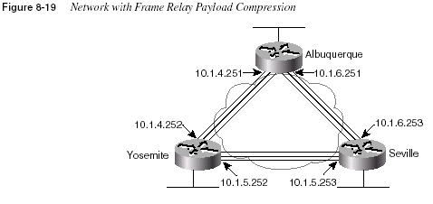
564
Chapter 8: WAN Protocols and DesignExample 8-21
Payload Compression Configuration, Albuquerquehostname Albuquerque
!
no ip domain-lookup
ipx routing 0200.aaaa.aaaa
!
interface Serial0
no ip address
encapsulation frame-relay IETF
frame-relay lmi-type cisco
!
interface Serial0.1 point-to-point
ip address 10.1.4.251 255.255.255.0
no ip directed-broadcast
ipx network 4
frame-relay interface-dlci 902 IETF
frame-relay payload-compression packet-by-packet
!
interface Serial0.2 point-to-point
ip address 10.1.6.251 255.255.255.0
no ip directed-broadcast
ipx network 6
frame-relay interface-dlci 903
!
interface Serial1
no ip address
no ip directed-broadcast
shutdown
!
interface Ethernet0
ip address 10.1.1.251 255.255.255.0
ipx network 1
!
router igrp 5
network 10.0.0.0
Example 8-22
Payload Compression Configuration, Yosemitehostname Yosemite
!
no ip domain-lookup
ipx routing 0200.bbbb.bbbb
!
interface Serial0
no ip address
encapsulation frame-relay IETF
frame-relay lmi-type cisco
!
interface Serial0.1 point-to-point
ip address 10.1.4.252 255.255.255.0
no ip directed-broadcast
ipx network 4
frame-relay interface-dlci 901 IETF
Frame Relay Configuration
565All that is necessary on the point-to-point subinterfaces to enable the Cisco STAC payload
compression is the
frame-relay payload-compression packet-by-packet interfacesubcommand on the subinterface on each end of the VC. Payload compression is enabled on a
per-VC basis, but because the subinterface is a point-to-point subinterface, only one VC is
allowed on the interface—that VC is implied as the one on which to perform compression.
If FRF.9 compression was desired instead, the
frame-relay payload-compression frf9 stacinterface subcommand would have been used. Using
frf9 stac as two separate keywords mightseem to imply that other options besides stac are available, but there are no other options. In
addition, you might think that the
stac keyword can be omitted, but it is required. You can thinkof
packet-by-packet as referring to the Cisco standard stac algorithm, and frf9 stac as referringto the FRF.9 standard.
The configuration when using a multipoint subinterface requires the use of the
frame-relaymap
command, even if Inverse ARP is used to automatically map the DLCIs to the Layer 3addresses. Examples 8-23 and 8-24 show a similar configuration for the network in Figure
8-20, except that the routers are now using multipoint subinterfaces. (Some unrelated
configuration details are not shown in these examples.)
frame-relay payload-compression packet-by-packet
!
interface Serial0.2 point-to-point
ip address 10.1.5.252 255.255.255.0
ipx network 5
frame-relay interface-dlci 903
!
interface Serial1
no ip address
shutdown
!
interface Ethernet0
ip address 10.1.2.252 255.255.255.0
ipx network 2
!
router igrp 5
network 10.0.0.0
Example 8-22
Payload Compression Configuration, Yosemite (Continued)566
Chapter 8: WAN Protocols and Design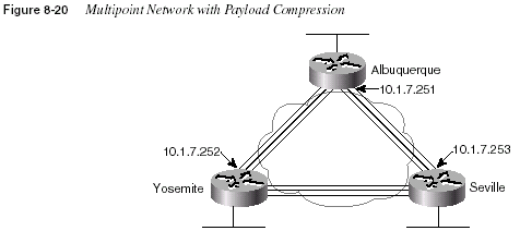
Example 8-23
Payload Compression Configuration, Albuquerque, Multipoint Subinterfaceshostname Albuquerque
!
interface Serial0
no ip address
encapsulation frame-relay IETF
frame-relay lmi-type cisco
!
interface Serial0.1 multipoint
ip address 10.1.7.251 255.255.255.0
no ip directed-broadcast
ipx network 7
frame-relay interface-dlci 902 IETF
frame-relay interface-dlci 903 IETF
frame-relay map ip 10.1.7.252 902 payload-compress frf9 stac
Example 8-24
Payload Compression Configuration, Yosemite, Multipoint Subinterfaceshostname Yosemite
!
interface Serial0
no ip address
encapsulation frame-relay IETF
frame-relay lmi-type cisco
!
interface Serial0.1 multipoint
ip address 10.1.7.252 255.255.255.0
no ip directed-broadcast
ipx network 7
frame-relay interface-dlci 901 IETF
frame-relay interface-dlci 903 IETF
frame-relay map ip 10.1.7.251 901 payload-compress frf9 stac
ISDN Protocols and Design
567All that is necessary on the multipoint subinterfaces on Yosemite to enable FRF.9 compression
on just the VC to Albuquerque is one interface subcommand on each of the two routers. The
frame-relay map ip 10.1.7.251 901 payload-compress frf9 stac
interface subcommand onYosemite tells the IOS for IP packets header out DLCI 901 to enable payload compression
and use the FRF.9 style of configuration. A similar command is used on Albuquerque—if
compression is disabled on only one end of the VC, or if a different type of compression is
enabled, then no packets will flow across the link.
If the Cisco STAC payload compression was desired instead, the
frf9 stac keywords wouldneed to be replaced by the
packet-by-packet keyword.ISDN Protocols and Design
The goal of this section is to summarize the details and to clarify complex features of ISDN and
related IOS functions. The CCNA exam focuses on Basic Rate Interface (BRI) functions, and
the CCNP and CCIE cover all of ISDN, including PRI.
ISDN Channels
Two types of ISDN interfaces are focused on in IOS documentation: Basic Rate Interface (BRI)
and Primary Rate Interface (PRI). Both BRI and PRI provide multiple digital bearer channels
over which temporary connections can be made and data can be sent. The result is digital dial
access to multiple sites concurrently. Table 8-24 summarizes the features of BRI and PRI.
Bearer channels (B channels) are used to transport data. B channels are called bearer channels
because they bear the burden of transporting the data. B channels operate at up to 64kbps,
although the speed might be lower depending on the service provider. The section “ISDN
Configuration,” later in the chapter, discusses how to configure the correct speed for the bearer
channels. D channels are used for signaling.
Table 8-24
BRI and PRI FeaturesType of Interface
Number of Bearer
Channels (B Channels)
Number of Signaling
Channels (D Channels)
BRI 2 1 (16kbps)
PRI (T/1) 23 1 (64kbps)
PRI (E/1) 30 1 (64kbps)
568
Chapter 8: WAN Protocols and DesignISDN Protocols
Coverage of ISDN protocols and their specifications on the CCNA exam poses a particularly
difficult problem for the CCNA candidate. The International Telecommunications Union (ITU)
defines the most well-known specifications for ISDN, but there are far more specifications than
anyone would want to try to memorize. The problem is choosing what to memorize and what
to ignore. My personal philosophy is that standards information is best kept in a book rather
than in my own memory. With Cisco’s emphasis on proving your hands-on skills using the
CCNA and CCNP exams, hopefully a de-emphasis on memorizing standards will be a
convenient side effect. However, these standards are fair game for the exam.
The characterizations of several key protocols made by the Cisco ICND course are important
for the exam. Table 8-25 is directly quoted from the ICND course. Take care to learn the
information in the Issue column—knowing what each series of specifications is about will be
useful.
The OSI layers correlating to the different ISDN specifications are also mentioned in both the
ITM and the ICND CCNA prerequisite courses. Memorizing the specifications in Table 8-26
and the OSI layer each specification matches is also useful.
Table 8-25
ISDN Protocol TableIssue Protocols Key Examples
Telephone network and ISDN E-series E.163: international telephone
numbering plan
E.164: international ISDN addressing
ISDN concepts, aspects, and
interfaces
I-series I.100 series: concepts, structures,
terminology
I.400 series: User-Network Interfaces
(UNI)
Switching and signaling Q-series Q.921: LAPD
Q.931: ISDN network layer
Table 8-26
ISDN I-Series and Q-Series Mentioned in ICND and ITM: OSI Layer ComparisonLayer, as
Compared to OSI I-Series
Equivalent
Q-Series
Specification General Purpose
1 ITU-T I.430
ITU-T I.431
Defines connectors, encoding, framing,
and reference points
2 ITU-T I.440
ITU-T I.4411
ITU-T Q.920
ITU-T Q.921
Defines the LAPD protocol used on the
D channel to encapsulate signaling
requests
ISDN Protocols and Design
569A tool to help you remember the specifications and layers is that the second digit in the Q-series
matches the OSI layer. For example, in ITU-T Q.920, the second digit, 2, corresponds to OSI
Layer 2. In the I-series, the second digit of the specification numbers is two more than the
corresponding OSI layer. For example, I.430, with the second digit of value 3, defines OSI
Layer 1 equivalent functions.
LAPD is used to deliver signaling messages to the ISDN switch—for example, a call setup
message. Figure 8-21 shows the use of LAPD versus PPP on B channels.
3 ITU-T I.450
ITU-T I.451
ITU-T Q.930
ITU-T Q.931
Defines signaling messages—for
example, call setup and takedown
messages
Table 8-26
ISDN I-Series and Q-Series Mentioned in ICND and ITM: OSI Layer Comparison (Continued)Layer, as
Compared to OSI I-Series
Equivalent
Q-Series
Specification General Purpose
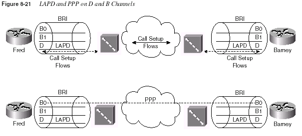
The call is established through the service provider network; PPP is used as the data link
protocol on the B channel from end to end. LAPD is used between the router and the ISDN
switch at each local central office (CO) and remains up so that new signaling messages can be
sent and received. Because the signals are sent outside the channel used for data, this is called
out-of-band signaling
.The BRI encodes bits at 192 kbps, with most of the bandwidth (144 kbps) being used for the
two B channels and the D channel. The additional bits are used for framing.
570
Chapter 8: WAN Protocols and DesignNOTE
For further reading, refer to the ITM course, available from Cisco for a nominal fee. (The ITMVersion 2 CD is based on Cisco Press’s
Internetwork Technology Handbook, 2nd Edition, ISBN:1-57870-102-3.)
The service profile identifier (SPID) used in signaling is important to the configuration of ISDN
and is likely to be mentioned on the exam. The SPID works like an ISDN phone number—in
fact, if buying ISDN for home use, the service provider personnel probably will call it the
ISDNphone number
instead of SPID. Call setup messages refer to both the called and the callingSPIDs. If a router wants to call another router, a SPID is used for call setup.
ISDN Function Groups and Reference Points
Many people are confused about the terms ISDN
reference point and ISDN function group. Onekey reason for the confusion is that only some function groups—and therefore some reference
points—are used in a single topology. Cisco expects CCNAs to be familiar with all function
groups and reference points. In an effort to clear up these two topics, consider the following
inexact but more familiar definitions of the two:
•
Function groups—A set of functions implemented by a device and software.•
Reference points—The interface between two function groups; this includes cablingdetails.
Most people understand concepts better if they can visualize a network or actually implement
the network. However, for a good understanding of function groups and reference points, keep
the following facts in mind:
•
Not all reference points are used in any one topology; in fact, one or two might never beused in a particular part of the world.
•
After the equipment is ordered and working, there is no need to think about functiongroups and reference points.
•
The router configuration does not refer to reference points and function groups, so manypeople ignore these details.
A cabling diagram is helpful for examining the reference points and the function groups. Figure
8-22 shows the cabling diagram for several examples.
ISDN Protocols and Design
571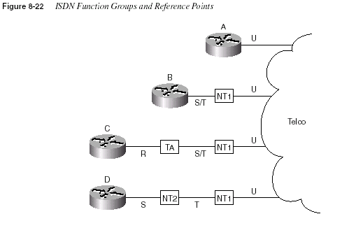
Router A was ordered with an ISDN BRI U reference point, referring to the I.430 reference
point defining the interface between the customer premise and the telco in North America.
Router B was bought with an ISDN BRI S/T interface, implying that it must be cabled to a
function group NT1 device in North America. An NT1 function group device must be
connected to the telco line through a U reference point in North America; the S/T interface
defines the connection to Router B. Router B is called a TE1 (Terminal Equipment 1) function
group device. Finally, non-ISDN equipment is called a TE2 (Terminal Equipment 2) device and
is attached using the R reference point to a terminal adapter (TA) function group device.
Alternately, a TE1 can connect using an S reference point to an NT2 function group, as shown
in case D of Figure 8-15.
Table 8-27 summarizes the types from Figure 8-22. Table 8-28 and Table 8-29 provide a
summary of formal definitions.
Table 8-27
Figure 8-22 Function Groups and Reference Point SummaryRouter Function Group(s)
Connected to Reference
Point(s)
A TE1, NT1 U
B TE1 S/T (combined S and T)
C TE2 R
D TE1 S
572
Chapter 8: WAN Protocols and DesignJargon definitely confuses the issue with home ISDN services. Figure 8-23 outlines the
problem.
Table 8-28
Definitions for Function Groups in Figure 8-22Function Group Acronym Stands for Description
TE1 Terminal Equipment 1 ISDN-capable four-wire cable. Understands
signaling, 2B+D. Uses S reference point.
TE2 Terminal Equipment 2 Equipment that does not understand ISDN
protocols and specifications (no ISDN
awareness). Uses R reference point, typically
an RS-232 or V.35 cable, to connect to a TA.
TA Terminal adapter Equipment that uses R and S reference points.
Can be thought of as the TE1 function group on
behalf of a TE2.
NT1 Network Termination
Type 1
CPE equipment in North America. Connects
with U reference point (two-wire) to telco.
Connects with T or S reference points to other
customer premise equipment.
NT2 Network Termination
Type 2
Equipment that uses a T reference point to the
telco outside North America, or to an NT1
inside North America. Uses an S reference
point to connect to other customer premise
equipment.
NT1/NT2 A combined NT1 and NT2 in the same device.
This is relatively common in North America.
Table 8-29
Definitions for Reference Points in Figure 8-22Reference Point Connection Between
R TE2 and TA.
S TE1 or TA and NT2.
T NT2 and NT1.
U NT1 and telco.
S/T TE1 or TA, connected to an NT1, when no NT2 is used. Alternately, the
connection from a TE1 or TA to a combined NT1/NT2.
ISDN Protocols and Design
573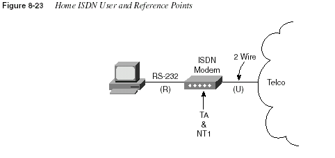
Popularly used, ISDN terminology for home-based consumers sometimes muddles the
terminology from the ISDN specifications. The home user orders the service, and the telco
offers to sell the user one of several “ISDN modems.” What is actually received is a TA and NT1
in one device. A PC uses a serial port to connect to the TA, which uses reference point R.
However, the terms reference point, TA, and NT1 are almost never used by providers, hence the
confusion.
One other detail of the ISDN protocols that might be on the exam is the ISDN SBus. The ISDN
SBus allows multiple devices to share the same BRI by sharing the S reference point. SBus is
a great idea, but it has not been deployed extensively. SBus takes the S reference point and
allows multiple TE1s to connect to the same NT1. This enables multiple TE1s to use the same
BRI. If all the TE1s were data devices, then instead of using an SBus, a better solution would
be to place all TE1s on a LAN and use an ISDN-capable router. To support ISDN phones, fax,
video, and data TE1 devices, however, the SBus can be used. Figure 8-24 shows a basic SBus
topology.
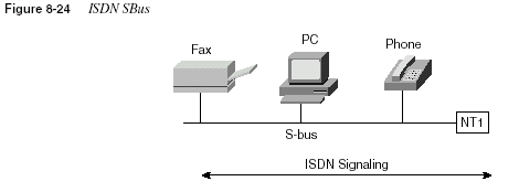
ISDN signaling can be created by the TE1s and responded to by TE1s. However, because the
BRI is shared among the TE1s, the SPID received in a call setup request no longer uniquely
identifies the TE1. Therefore, a suffix called a
subaddress is added to the SPID. Each TE1 onthe SBus uses a different subaddress. The service provider connected to this NT1 and to any
other NT1 from which calls are set up must support subaddressing before the user can use SBus.
574
Chapter 8: WAN Protocols and DesignTypical Use of ISDN
ISDN typically is used for temporary dial connections. Attractive pricing has also caused some
companies to use permanently dialed (“nailed-up”) ISDN connections instead of leased lines.
ISDN lines can provide access at 128kbps, using both B channels. Compression can increase
throughput, potentially getting 500kbps of throughput through the line. xDSL technology is an
emerging competitor to ISDN for dial-in ISPs.
Temporary connections between routers are another typical use of ISDN, both for backup and
for occasional connection. Backup is self-explanatory. Occasional connections would include
traffic for sites that do not use online applications or video conferencing, and cases in which
additional bandwidth between sites is desired. Most of the configuration needed for these
occasional connections is related to a topic called
dial-on-demand routing (DDR), which iscovered in a later section of this chapter. Figure 8-25 shows some of the typical network
topologies when using ISDN.
The scenarios in Figure 8-25 can be described as follows:
•
Case 1 shows dial-on-demand routing. Logic is configured in the routers to trigger the dialwhen the traffic that needs to get to another site is sent by the user.
•
Case 2 shows a typical telecommuting environment.•
Case 3 shows the typical dial-backup topology. The leased line fails, so an ISDN call isestablished between the same two routers.
•
Case 4 shows a case in which an ISDN BRI could be used to dial directly to another routerto replace a Frame Relay access link or a failed VC.
•
Case 5 depicts an ISDN line that could be used to dial into the Frame Relay provider’snetwork, replacing a failed VC or access link with a VC running over an ISDN connection
to the Frame Relay switch.
PAP and CHAP
PPP and HDLC can be used on B channels, but PPP provides several features that make it the
preferred choice in a dial environment. HDLC and PPP overhead per-data frame is identical;
however, PPP provides LQM, as well as CHAP and PAP authentication and Layer 3 address
assignment through several of the control protocols. Each of these features is particularly
important in a dial environment.
Password Authentication Protocol (PAP) and Challenge Handshake Authentication Protocol
(CHAP) are used to authenticate (verify) that the endpoints on a dial connection are allowed to
connect. CHAP is the preferred method today because the identifying codes flowing over the
link are created using a Message Digest 5 (MD5) one-way hash, which is more secure than the
clear-text passwords sent by PAP.
ISDN Protocols and Design
575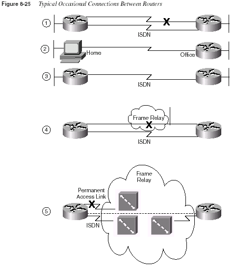
Both PAP and CHAP require the exchange of messages between devices. The dialed-to router
expects to receive a user name and password from the dialing router with both PAP and CHAP.
With PAP, the user name and password are sent by the dialing router. With CHAP, the dialedto
router sends a message (called a challenge) that asks the dialing router to send its user name
and password. The challenge includes a random number, which is part of the input into the MD5
hash algorithm. The dialing router replies with the MD5 hash value, which is a function of its
ID (host name), its password, and the random number supplied in the challenge. The dialed-to
router repeats the same hash algorithm; if the received value matches the computed value, the
576
Chapter 8: WAN Protocols and DesignCHAP authentication is passed. Figure 8-26 illustrates the message flow in PAP and CHAP
environments. Example 8-25 shows the CHAP configuration for Figure 8-26.
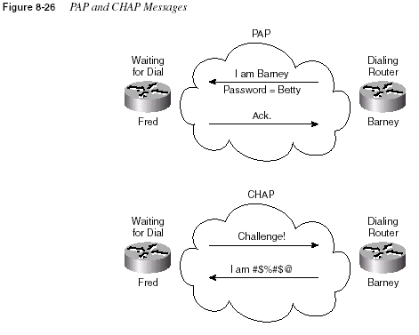
Notice that each router refers to the other router’s host name; each router uses its own host name
in CHAP flows, unless overridden by configuration. Each codes the same password. When
Router Barney receives a challenge from Router Fred, Router Barney sends an encrypted value,
which is the value Fred should compute given the name Barney, the password Bedrock, and the
original random number. CHAP authentication is completed if the two values match.
Example 8-25
CHAP Configuration SampleRouter Fred Router Barney
username Barney password Bedrock username Fred password Bedrock
! !
Interface serial 0 Interface serial 0
encapsulation ppp encapsulation ppp
ppp authentication chap ppp authentication chap
. .
ISDN Protocols and Design
577Multilink PPP
Multilink PPP is a function that allows multiple links between a router and some other device
over which traffic is balanced. The need for this function is straightforward; some other
considerations about when to use it are subtle. Figure 8-27 illustrates the most obvious need for
Multilink PPP.

Figure 8-27 shows two dotted lines between the PC and the access server, signifying that two
B channels are in use between the devices. Multilink PPP breaks a packet into fragments, sends
some fragments across each of the two links, and reassembles them at the other end of the link.
The net result is that the links are utilized approximately the same amount.
Multilink PPP is also useful between routers. For example, in Figure 8-28, videoconferencing
between Atlanta and Nashville uses six B channels between two routers.

In this example, if multilink PPP is used, the links have almost identical utilization. The
negative is that the routers must fragment and reassemble every packet. However, the 384Kb
needed for the video conference is available.
Now consider the alternative—without multilink PPP, but simply with PPP on each of the six
links. Six routes to subnet 10.2.2.0/24 would exist in Router A’s routing table. With any of the
faster internal switching methods in a Cisco router (fast switching, optimum switching,
NetFlow switching), the balancing effect is that
all packets to the same IP address use the samelink
. The result is that router Atlanta sends some packets over one link and some over the other,but the balancing is unpredictable. More importantly, all packets to the videoconference
system’s single IP address in Nashville will use the same link, effectively limiting the
videoconference to 64 kbps. An alternative is to disable the faster switching methods in the
router so that multiple routes to the same subnet are used in a round-robin fashion. However,
578
Chapter 8: WAN Protocols and Designthat is not recommended because it significantly slows the internal processing on the router. For
that reason, multilink PPP is a better choice in this case.
Example 8-26 shows a sample multilink PPP configuration. The Atlanta and Nashville routers
will use two B channels of the same BRI.
The two key commands are the
ppp multilink and the dialer load-threshold commands. pppmultilink
enables multilink PPP; dialer load-threshold tells the router to dial another Bchannel if the utilization average on the currently used links is more than 25 percent for either
inbound or outbound utilization.
Dial-on-Demand Routing and ISDN Configuration
As a CCNA, you’ll need to understand both ISDN configuration and the related DDR
configuration that causes the IOS to use the BRI interface. Dial-on-demand routing (DDR)
configuration and concepts must be understood before the ISDN configuration topics will make
complete sense. In fact, ISDN configuration can be very brief, whereas DDR can become quite
involved. In this section, DDR is explained first, with ISDN configuration included later.
DDR defines the logic behind when a router chooses to dial another site, whether ISDN,
synchronous serial, or asynchronous serial interfaces are used. In this chapter, the examples
reflect ISDN; the DDR logic is the same for any of the three types of dial interfaces. DDR
includes several variations; the variation called DDR legacy is covered in this chapter. Those of
you who want to pursue CCNP and CCIE certification should expand your knowledge of DDR
concerning DDR dialer profiles in particular.
Little additional ISDN configuration is required in addition to the core DDR configuration. In
fact, one detail that is covered deeply in the earlier ISDN concepts section is the use of certain
reference points by Cisco’s products; there is no need to configure the IOS to know which
interface is used. Cisco’s BRI implementation includes a choice of an S/T interface or a U
interface. In either case, BRI configuration in the router is identical.
Hands-on experience is the best way to fully learn the details of configuration. In lieu of that,
this section lists commands, provides examples, and points out tricky features. Table 8-30 and
Example 8-26
Multilink PPP Configuration for Atlantausername Nashville password Robert
interface bri 0
ip addr 10.3.3.1 255.255.255.0
encapsulation ppp
dialer idle-timeout 300
dialer load-threshold 25 either
dialer map 10.3.3.2 name Nashville 16155551234
dialer-group 1
ppp authentication chap
ppp multilink
Dial-on-Demand Routing and ISDN Configuration
579Table 8-31 summarize the more popular commands used for ISDN configuration and
verification. The Cisco IOS documentation is an excellent reference for additional IP
commands, and the Cisco Press book
Interconnecting Cisco Network Devices is another goodreference, particularly if you are not able to attend the instructor-led version of the class.
Table 8-30
ISDN Configuration CommandsCommand Configuration Mode Purpose
isdn switch-type
switch-type Global or interface Defines to the router the type of ISDNswitch to which the ISDN line is
connected at the central office.
isdn spid1
spid Interface Defines the first SPID.isdn spid2
spid Interface Defines the second SPID.isdn caller
number Interface Defines a valid number for incomingcalls when using call screening.
isdn answer1
[called-partynumber][:subaddress
]Interface Specifies the ISDN number or
subaddress that must be used on
incoming calls for this router to
answer.
isdn answer2
[called-partynumber][:subaddress
]Interface Specifies a second ISDN number or
subaddress that must be used on
incoming calls for this router to
answer.
dialer-list
[list nnn] protocol[
protocol-type] permit | denyGlobal Defines types of traffic considered
interesting.
dialer-group
n Interface Enables dialer list on this interface.dialer in-band
Interface Enables dial out and dial in on thisinterface. This command is used only
for serial lines that connect to a TA,
not for native ISDN interfaces that use
the out-of-band D channel.
dialer string
string Interface Is the dial string used when dialingonly one site.
dialer map
protocol nexthopaddress
[namehostname
] [speed 56 | 64][broadcast]
dial-stringInterface Is the dial string to reach the next hop.
However, the
map command is usedwhen dialing more than one site. This
also is the name used for authentication.
Broadcast ensures that copies
of broadcasts go to this next-hop
address.
580
Chapter 8: WAN Protocols and DesignDDR Legacy Concepts and Configuration
Two ways exist by which to configure DDR. The two styles of DDR configuration are called
DDR legacy
and DDR dialer profiles. The main difference between the two is that DDR legacyassociates dial details with a physical interface, but DDR dialer profiles-style configuration
disassociates the dial configuration from a physical interface, allowing a great deal of flexibility.
The concepts behind legacy DDR apply to DDR dialer profiles as well, but DDR legacy is a
little less detailed. Although not overly stated in the course, the DDR coverage in the ICND
class is for DDR legacy.
DDR can be used to cause the router to dial or to receive a dial on asynchronous serial
interfaces, synchronous serial interfaces, and ISDN BRI and PRI interfaces. All examples in
this chapter use ISDN BRI.
The following list identifies the four key concepts behind DDR configuration. The first two
concepts are not actually related to the dial process, but relate to the process of choosing when
to dial and when not to dial. The other two concepts relate to dialing, or signaling. The term
signaling
is used in ISDN to describe the processes of call setup and takedown, and it is usedsynonymously with the term
dialing here. The four key concepts are as follows:Step 1
Routing packets out of the to-be-dialed interfaceStep 2
Determining the subset of these packets that trigger the dialingprocess
Table 8-31
ISDN-Related EXEC CommandsCommand Function
show interfaces bri
number
[:b-channel]Includes reference to the access lists enabled on the interface.
show controllers bri
number Shows Layer 1 statistics and status for B and D channels.show isdn
{active | history |memory
| status | timers}Shows various ISDN status information.
show interfaces bri
number
[[:bchannel] | [first][
last]] [accounting]Displays interface information about the D channel or the B
channel(s).
show dialer interface bri
number
Lists DDR parameters on the BRI interface. Shows whether currently
dialed by indicating current status. Also shows previous attempts to
dial and whether they were successful.
debug isdn q921
Lists ISDN Layer 2 messages.debug isdn q931
Lists ISDN Layer 3 messages (call setup/teardown).debug dialer
{events |packets
}Lists information when a packet is directed out a dial interface, telling
whether the packet is interesting.
Dial-on-Demand Routing and ISDN Configuration
581Step 3
Dialing (signaling)Step 4
Determining when the connection is terminatedEach of these is addressed in succession, followed by a discussion of DDR legacy
configuration. After learning about the basic DDR concepts and configuration procedures, you
will learn about ISDN-specific configuration. Finally, this section concludes with a complete
DDR and ISDN example.
DDR Step 1: Routing Packets out the Interface to Be Dialed
Figure 8-29 provides the backdrop for these discussions. In these discussions, the SanFrancisco
router will be dialing into the main site in LosAngeles.

The router must choose when to dial. The first step in this process relates to the following fact:
DDR will not dial until some traffic is directed (routed) out the dial interface.
The router needs to route packets so that they are queued to go out the dial interface. Cisco’s
design for DDR defines that the router receives some user-generated traffic and, through normal
routing processes, decides to route the traffic out the interface to be dialed. The router
(SanFrancisco) can receive a packet that must be routed out BRI0; routing the packet out BRI0
triggers the IOS, causing the dial to occur.
Of course, routes are not learned over a dial link while the dial link is down. In Figure 8-29, for
instance, SanFrancisco will have no routes to 172.16.3.0/24 learned via a routing protocol.
Therefore, static routes are configured on SanFrancisco. This can be done for any protocol that
is supported by DDR for the purpose of triggering the dial. All routable protocols can be
configured to trigger the dial; IP will be used in the upcoming examples. Any traffic that could
be routed or bridged across a leased link is supported after the link is up.
To begin the process of building a DDR configuration, IP routes are added to the configuration
so that packets can be directed out BRI0 on SanFrancisco:
! SanFrancisco Static routes.
ip route 172.16.3.0 255.255.255.0 172.16.2.1
582
Chapter 8: WAN Protocols and DesignDDR Step 2: Determining the Subset of The Packets That Trigger the Dialing Process
Together, Steps 1 and 2 of legacy DDR logic determine when the dial is attempted. These
combined steps are typically called
triggering the dial. In Step 1, a packet is routed out aninterface to be dialed, but that packet alone does not necessarily cause the dial to occur. The IOS
allows the second step to define a subset of the packets routed in Step 1 to actually cause the
route to dial. The logic flow works as shown in Figure 8-30.
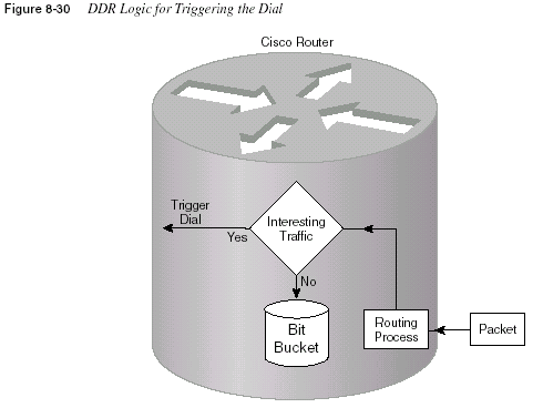
The choice in Step 2 is simply put like this: “Is this packet, which is being routed out this dial
interface, worthy of causing the dial to occur?” The packets that are worthy of causing the
device to dial are called
interesting packets by Cisco. Cisco does not categorize those packetsthat are not worthy of causing the dial; in effect, they are “boring.” The capability to exactly
determine the interesting packets grants the router administrator control over when the dial is
made. This is particularly important if the dialed connection is incrementally charged by the
minute.
Two different methods can be used to define the interesting packets.
Interesting can be definedas all packets of one or more Layer 3 protocols (for example, all IP packets). In that case, any
user in SanFrancisco can send a packet to any host in 172.16.3.0/24 and trigger the dial
connection. That might be exactly what is desired, or it might not be. The second method is that
interesting
can be defined as packets permitted by an access list. In this case, if the access listpermits the packet, it is considered interesting.
Dial-on-Demand Routing and ISDN Configuration
583Example 8-27 shows additional configuration on SanFrancisco, in two cases. One shows all IP
packets being considered as interesting, and the other shows all packets to the Web server Lois
(refer to Figure 8-29) considered as interesting.
The
dialer-group interface subcommand enables the logic that determines what is interesting.It refers to a dialer list, which can refer either to an entire protocol suite or to an access list, as
shown. (After the link is up, packets are not filtered using list 101—the logic is used just for
determining what is interesting and what is boring.)
DDR Step 3: Dialing (Signaling)
The dialing router needs additional information before the dial can occur. First, for non-ISDN
interfaces, it is necessary to communicate the dial string to the external dialing device. In-band
signaling (dialing) must be enabled on these interfaces using the command
dialer in-band.This is not necessary on a BRI interface because it uses the out-of-band D channel for signaling.
Table 8-32 summarizes what the command implies on different interfaces.
The second piece of information needed before dialing is the phone number. With the network
in Figure 8-29, the configuration is straightforward. The command is
dialer string string,where
string is the phone number. Example 8-28 completes the DDR configuration associatedwith Figure 8-29 that allows the dial to occur.
Example 8-27
Defining Interesting Packets to Activate the Circuit from SanFrancisco to LosAngelesip route 172.16.3.0 255.255.255.0 172.16.2.1
access-list 101 permit tcp any host 172.16.3.1 eq 80
dialer-list 1 protocol ip permit
dialer-list 2 protocol ip list 101
interface bri 0
encapsulation ppp
ip address 172.16.2.2 255.255.255.0
!Use this one if all IP is considered interesting ...
dialer-group 1
! OR Use next statement to trigger for Web to Server Lois
dialer-group 2
Table 8-32
Effect of the dialer in-band CommandType of Interface Type of Signaling Used
Async AT command set (in-band)
Sync V.25 bis (in-band)
ISDN ISDN D channel with Q.921/Q.931 (out-of-band)
584
Chapter 8: WAN Protocols and DesignThe
dialer in-band command is omitted because an ISDN BRI is used in this case. The onlynew command added here is the
dialer string command, which shows the phone number thatis to be used for signaling a connection. The signaling occurs on the D channel of the BRI.
When more than one site is dialed from the same interface, several dial strings are needed.
For example, Figure 8-31 adds a third site, GothamCity, to the network. The client’s FTP
connections to the FTP server running on Commissioner will be considered interesting traffic
for causing dial connections to GothamCity.
Example 8-28
SanFrancisco Configuration—Dial Now Can Occurip route 172.16.3.0 255.255.255.0 172.16.2.1
!
access-list 101 permit tcp any host 172.16.3.1 eq 80
!
dialer-list 2 protocol ip list 101
!
interface bri 0
ip address 172.16.2.2 255.255.255.0
encapsulation ppp
dialer string 14045551234
dialer-group 2
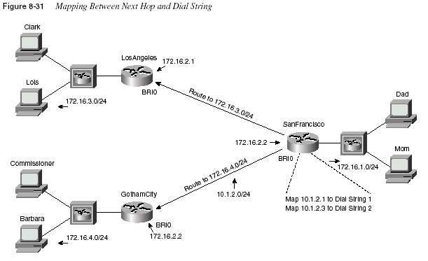
Dial-on-Demand Routing and ISDN Configuration
585The dilemma for SanFrancisco will now be how to determine which ISDN telephone number
to signal. The key is in the
ip route commands and the new dialer map command. Of course,there are unique ISDN telephone numbers for both LosAngeles and GothamCity. Because the
static routes will direct the router to send the packet to either 172.16.2.1 or 172.16.2.3, all that
is needed is a mapping between these next-hop addresses and their respective ISDN telephone
numbers. The
dialer map command does exactly that. Example 8-29 shows the mostlycomplete configuration.
The
dialer map commands imply that if the interesting packet were routed to 172.16.2.1, thedial to LosAngeles would occur. Conversely, if the interesting packet were routed to 172.16.2.3,
the dial to GothamCity would occur. The definition of
interesting is expanded to include packetsto the FTP server in GothamCity.
Two other important configuration elements are included in Example 8-28. First, CHAP
authentication was configured. PAP or CHAP is required if dialing to more than one site with
ISDN—and PAP and CHAP require PPP. The user name expected from the other router is
coded in the corresponding
dialer map command.Broadcast handling is the final configuration element that must be addressed. Just as with any
other point-to-point serial link, there is no true data link broadcast. If a broadcast must be sent
on the interface, however, it is necessary to issue the
broadcast command to tell the interfaceto forward the packet across the link.
Example 8-29
SanFrancisco Configuration—Two Dial-to Sites, dialer map in Useip route 172.16.3.0 255.255.255.0 172.16.2.1
ip route 172.16.4.0 255.255.255.0 172.16.2.3
! Added usernames for CHAP support!
username LosAngeles password Clark
username GothamCity password Bruce
access-list 101 permit tcp any host 172.16.3.1 eq 80
! Added next statement to make The Client’s FTP connection interesting!
access-list 101 permit tcp any host 172.16.4.1 eq 21
!
dialer-list 2 protocol ip list 101
!
interface bri 0
ip address 172.16.2.2 255.255.255.0
encapsulation ppp
ppp authentication chap
dialer map ip 172.16.2.1 broadcast name LosAngeles 14045551234
dialer map ip 172.16.2.3 broadcast name GothamCity 1999999999901
dialer-group 2
!
router igrp 6
network 172.16.0.0
586
Chapter 8: WAN Protocols and DesignDDR Step 4: Determining When the Connection Is Terminated
The dialed link acts just like a leased line while it is up. If a particular Layer 3 protocol is
enabled on the link, it can be routed across the link. Transparent (encapsulated) bridging can be
used just like any other point-to-point link. Routing updates, IPX SAPs, AppleTalk ZIP, and
other broadcasts are sent across the link if the
broadcast keyword is coded. Most importantly,any access list used to define which packets are interesting does not filter the traffic on the
interface. If packet filters are desired, an access list must be enabled on the interface.
Additional parallel links can be dialed if more capacity is desired. To do so, dialer profiles must
be configured. Additionally, the
dialer load-threshold load command is used to define the linkutilization that must be exceeded for another link to be dialed.
The decision to take the link down is the most intriguing part about what happens while the link
is up. Although any type of packets can be routed across the link, only interesting packets are
considered worthy of keeping the link up. An idle timer counts the time since the last interesting
packet went across the link. If that time expires, the link is brought down.
Two idle timers can be set. With the
dialer idle-timeout seconds command, the idle time aspreviously described is set. If interesting traffic that needs to flow to another dial site is
occurring, however, another shorter idle timer can be used. The
dialer fast-idle secondscommand enables you to configure a typically lower number than the idle timer so that when
other sites need to be dialed, the link that is currently up but can be brought down earlier in the
process of idling out as per the
dialer idle-timeout command.ISDN Configuration
Example 8-30 and Example 8-31 show the DDR configuration for the network in Figure 8-31.
ISDN configuration details have been added; the text following these two examples describes
the ISDN commands shown.
Example 8-30
SanFrancisco Configuration—Completeip route 172.16.3.0 255.255.255.0 172.16.2.1
ip route 172.16.4.0 255.255.255.0 172.16.2.3
! Added usernames for CHAP support!
username LosAngeles password Clark
username GothamCity password Bruce
!
access-list 101 permit tcp any host 172.16.3.1 eq 80
access-list 101 permit tcp any host 172.16.4.1 eq 21
!
dialer-list 2 protocol ip list 101
!
interface bri 0
encapsulation ppp
ppp authentication chap
isdn spid1 555555111101
isdn spid2 555555222202
dialer idle-timeout 300
Dial-on-Demand Routing and ISDN Configuration
587The ISDN configuration commands are delineated in the examples via highlighted text; those
commands are described in the upcoming text. For example, the switch types are a required
parameter for connection to DMS-100 or National ISDN switches; ask your service provider
for the type of switch at each site. The LosAngeles BRI is attached to a National ISDN switch
in this case. The switch type can be configured with the
isdn switch-type command, which canbe used as a global command, or with an interface subcommand if the router is connected to
multiple different types of ISDN switches. The SPIDs might not be required; they are used
as a form of authentication by the switch. The SPIDs are configured with BRI interface
subcommands on SanFrancisco. Also, hidden in part of the DDR configuration, the speed of the
B channel from SanFrancisco to GothamCity will be 56kbps, according to the speed parameter
in the
dialer map command on SanFrancisco.PAP or CHAP authentication is required for ISDN BRI dial connections. PAP and CHAP
configuration is covered earlier in this chapter, in the section “PAP and CHAP.”
As seen in Example 8-32, a DDR dial connection over BRI0 has occurred from SanFrancisco
to LosAngeles:
dialer fast-idle 120
dialer map ip 172.16.2.1 broadcast name LosAngeles 14045551234
dialer map ip 172.16.2.3 broadcast speed 56 name GothamCity 1999999999901
dialer-group 2
!
router igrp 6
network 172.16.0.0
Example 8-31
LosAngeles Configuration—Receive Onlyusername SanFrancisco password Clark
!
interface bri 0
encapsulation ppp
ppp authentication chap
isdn switch-type basic-ni1
!
router igrp 6
network 172.16.0.0
Example 8-32
SanFrancisco DDR commandsSanFrancisco#
show interfaces bri 0:1BRI0:1 is down, line protocol is down
Hardware is BRI
MTU 1500 bytes, BW 64 Kbit, DLY 20000 usec, rely 255/255, load 1/255
Encapsulation PPP, loopback not set, keepalive set (10 sec)
LCP Open
Open: IPCP, CDPCP
Last input 00:00:05, output 00:00:05, output hang never
Example 8-30
SanFrancisco Configuration—Complete (Continued)continues
588
Chapter 8: WAN Protocols and DesignLast clearing of “show interface” counters never
Input queue: 0/75/0 (size/max/drops); Total output drops: 0
Queuing strategy: weighted fair
Output queue: 0/1000/64/0 (size/max total/threshold/drops)
Conversations 0/1/256 (active/max active/max total)
Reserved Conversations 0/0 (allocated/max allocated)
5 minute input rate 0 bits/sec, 0 packets/sec
5 minute output rate 0 bits/sec, 0 packets/sec
44 packets input, 1986 bytes, 0 no buffer
Received 0 broadcasts, 0 runts, 0 giants, 0 throttles
0 input errors, 0 CRC, 0 frame, 0 overrun, 0 ignored, 0 abort
49 packets output, 2359 bytes, 0 underruns
0 output errors, 0 collisions, 7 interface resets
0 output buffer failures, 0 output buffers swapped out
11 carrier transitions
DCD=up DSR=up DTR=up RTS=up CTS=up
SanFrancisco#
show dialer interface bri 0BRI0 - dialer type = ISDN
Dial String Successes Failures Last called Last status
0 incoming call(s) have been screened.
BRI0: B-Channel 1
Idle timer (300 secs), Fast idle timer (120 secs)
Wait for carrier (30 secs), Re-enable (15 secs)
Dialer state is data link layer up
Dial reason: ip (s=172.16.1.1, d=172.16.3.1)
Time until disconnect 18 secs
Current call connected 00:14:00
Connected to 14045551234 (LosAngeles)
BRI0: B-Channel 2
Idle timer (300 secs), Fast idle timer (120 secs)
Wait for carrier (30 secs), Re-enable (15 secs)
Dialer state is idle
SanFrancisco#
show isdn active-------------------------------------------------------------------------------
ISDN ACTIVE CALLS
-------------------------------------------------------------------------------
History Table MaxLength = 320 entries
History Retain Timer = 15 Minutes
-------------------------------------------------------------------------------
Call Calling Called Duration Remote Time until Recorded Charges
Example 8-32
SanFrancisco DDR commands (Continued)Dial-on-Demand Routing and ISDN Configuration
589The current timer values and call setup reason are listed by the first command in Example 8-32,
show dialer interface bri 0
. The call has been up for 14 minutes, and 18 seconds are left beforethe 300-second inactivity timer will expire and take the connection down. The
show isdn activecommand lists the fact that a single active call exists to LosAngeles, with now only 11 seconds
left until disconnect. The
show isdn status command lists the switch type (ntt) and lists the factthat one call is active, which leaves one inactive B channel.
Remembering the general idea behind the debug command output is also useful for CCNAs so
that the right options can be enabled quickly. The
debug isdn q921 command (not shown) listsType Number Number Seconds Name Disconnect Units/Currency
-------------------------------------------------------------------------------
Out 14045551234 Active(847) LosAngeles 11 u
-------------------------------------------------------------------------------
SanFrancisco#
show isdn statusThe current ISDN Switchtype = ntt
ISDN BRI0 interface
Layer 1 Status:
ACTIVE
Layer 2 Status:
TEI = 64, State = MULTIPLE_FRAME_ESTABLISHED
Layer 3 Status:
1 Active Layer 3 Call(s)
Activated dsl 0 CCBs = 1
CCB:callid=8003, callref=0, sapi=0, ces=1, B-chan=1
Number of active calls = 1
Number of available B-channels = 1
Total Allocated ISDN CCBs = 1
SanFrancisco#
debug isdn q931ISDN q931 protocol debugging is on
TX -> SETUP pd = 8 callref = 0x04
Bearer Capability i = 0x8890
Channel ID i = 0x83
Called Party Number i = 0x80, `14045551234’
SanFrancisco#
no debug allAll possible debugging has been turned off
SanFrancisco#
debug dialer eventsDialer event debugging is on
Dialing cause: BRI0: ip (s=172.16.1.1, d=172.16.3.1)
SanFrancisco#
no debug allAll possible debugging has been turned off
SanFrancisco#
debug dialer packetsDialer packet debugging is on
BRI0: ip (s=172.16.1.1, d=172.16.3.1) 444 bytes, interesting (ip PERMIT)
Example 8-32
SanFrancisco DDR commands (Continued)590
Chapter 8: WAN Protocols and Designdetails of the LAPD protocol between the router and the ISDN switch. The
debug isdn q931command lists output for call setup and disconnect; the output in the example shows output
typical of what happened on SanFrancisco when the call to LosAngeles was made. The
debugdialer events
and debug dialer packets commands provide similar information when a packetis a candidate for causing the dial to occur—in other words, when a packet is routed out the dial
interface.
A Comparison of WAN Options
Networking professionals need to know about many WAN options when designing networks.
Certainly, Cisco requires CCNAs to have a solid foundation of the WAN technologies in this
chapter. Cisco also expects CCNAs to be able to compare and contrast these different WAN
technologies. This section summarizes many of the concepts found earlier in this chapter, with
a focus on comparison.
The permanent WAN connectivity options can be categorized into two main groups:
synchronous serial leased lines and packet switching services. PPP, HDLC, and LAPB are
the three data link protocols most typical on leased lines, with Frame Relay being the most
pervasive packet-switched service. In fact, Frame Relay is better named a
frame switchingservice to imply that the protocol is a Layer 2 protocol, but when talking similar services as a
group,
packet switching is the typical term used. X.25 and ATM services also fall into the packetswitching category.
X.25 and ATM are not discussed in this exam guide in any depth. (For more information, refer
to the documents referenced in Appendix B, “Decimal to Hexadecimal and Binary Conversion
Table.”) X.25 is very similar to Frame Relay because it uses VCs and has error-recovery built
in to each link and each end-to-end VC. ATM is similar in its use of virtual connections, which
are conceptually equivalent to VCs. However, ATM includes the concept of segmentation and
reassembly (SAR), in which the device at the edge of the ATM network breaks the frames to be
sent into smaller cells (53 bytes) that are reassembled at the other end of the VC. The details of
how each of these three packet-switching protocols are implemented is different; however, each
creates a multiaccess network, with direct packet forwarding allowed only between pairs of
devices that have a VC between them.
Table 8-33 summarizes these types of permanent connections and lists some of the strengths
and weaknesses.
A Comparison of WAN Options
591The product selection phase on any design project can and should necessarily include key
individuals from the organization that will be purchasing or leasing the hardware, Cisco (or the
reseller), and any contracted service companies participating in the future deployment of the
new equipment. (Some of you probably fall into each of those categories, and possibly into
several.) When choosing products, having the vendor or reseller involved can help avoid the
problem of trying to be aware of all possible products and options, particularly for new or
impending products.
To combat some of the challenges of choosing products from a widely varied product line,
Cisco developed the use of three key words to describe the type of product deployed in a typical
enterprise network: Core, Distribution, and Access. Figure 8-32 provides a basic network, and
Table 8-34 summarizes the meaning behind these three categorizations.
Table 8-33
Comparison of Leased Versus Packet SwitchingType of WAN
Service
Data Link
Protocols Strengths and Weaknesses
Leased Delivers pervasive availability. Can be expensive for long
circuits. Is more expensive for providers to engineer than are
packet services.
PPP Can improve speed of routing protocol convergence. Allows
multivendor interoperability. Has available error recovery
option.
HDLC Is the IOS default. Requires Cisco router on each end.
LAPB Provides error recovery, but this also can result in throttling
(slowing) the data rate.
Packet-switched Allows addition of new sites to be made quickly. Typically
involves a lower cost.
Frame Relay Allows bursting past CIR, giving perception of “free”
capacity. Is pervasive in the United States.
ATM As a WAN technology, is not as pervasively available as
Frame Relay. Has an attractive built-in Quality of Service
feature.
X.25 Is available pervasively in some parts of the world. Offers
beneficial error-recovery features when links have higher
error rates. Typically is the third choice of these three if all
are available to all connected sites.
592
Chapter 8: WAN Protocols and Design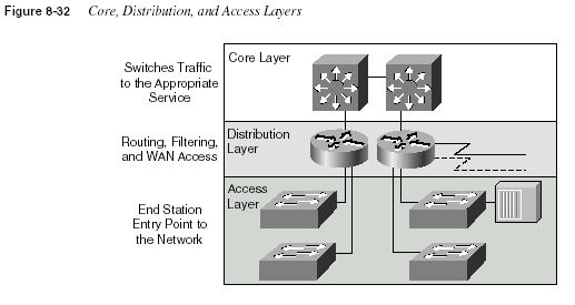
Cisco expects CCNAs to understand the needs of each of these layers in a typical network.
Conveniently, if router product numbers are listed from low numbers to high, the products that
tend to be listed first are access routers, then distribution, and then core, for the most part. For
instance, Figure 8-33 comes directly from the ICND course, which is one of the two suggested
prerequisites for the CCNA exam. The figure lists the main product families.
Table 8-34
Comparison of Core, Distribution, and Access LayersLayer Features Desired Device Characteristics
Core Fast transport, often at the topological
center of the network. Packet
manipulation is not performed here.
Highest forwarding speed
Distribution Aggregation of access points. Any
media translation or security (for
instance, access lists) is performed
here.
High interface density, high processing
capacity per interface for packet
manipulation
Access Entry point for end-user devices, both
LAN and dial.
High variety of interface types, less
processing capacity required (versus
distribution)
A Comparison of WAN Options
593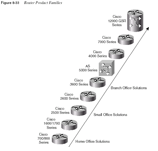
Many of the lower-end routers have both BRI interfaces and asynchronous support (1700, 2600,
and 3600), so these would make excellent access routers. The 3600 and 4000 series have more
port density than the smaller routers and have RISC processors for better performance on packet
manipulation. Finally, the 7000 series, which includes the 7200 and 7500 routers, and the
Gigabit Switch Router (GSR) provide the highest forwarding capacity.
All these routers support synchronous serial interface, which can be configured for PPP, HDLC,
LAPB, Frame Relay, and X.25. ATM requires a specific interface due to the SAR function. For
instance, the 3600 series supports ATM support at OC-3 speeds and higher; some slower ATM
interfaces are supported on access routers.
594
Chapter 8: WAN Protocols and DesignFoundation Summary
The Foundation Summary is a collection of tables and figures that provide a convenient review
of many of the key concepts in this chapter. For those of you already comfortable with the topics
in this chapter, this summary could help you recall a few details. For those of you who just read
this chapter, this review should help solidify some key facts. For any of you doing your final
prep before the exam, these tables and figures will hopefully be a convenient way to review the
day before the exam.
Table 8-35 summarizes the configuration commands used for HDLC and PPP configuration:
Table 8-36 summarizes the more popular commands used for Frame Relay configuration.
Table 8-35
PPP and HDLC Configuration CommandsCommand Configuration Mode
encapsulation
{hdlc | ppp | lapb} Interface subcommandcompress
[predictor | stac | mppc [ignore-pfc]] Interface subcommandTable 8-36
Frame Relay Configuration CommandsCommand
Configuration
Mode Purpose
encapsulation framerelay
[
ietf | cisco]Interface Defines Frame Relay encapsulation; is used
rather than HDLC, PPP, and so on.
frame-relay lmi-type
{
ansi | q933a | cisco}Interface Defines the type of LMI messages sent to the
switch.
bandwidth
num Interface Sets the route’s perceived speed of the interface.Bandwidth is used by some routing protocols to
influence the metric.
frame-relay map
protocolprotocol-address dlci
[
payload-compress{
packet-by-packet | frf9stac
}] [broadcast] [ietf |cisco
]Interface Statically defines a mapping between a network
layer address and a DLCI.
keepalive
sec Interface Defines whether and how often LMI statusenquiry messages are sent and expected.
interface serial
num.sub[
point-to-point |multipoint
]Global Creates a subinterface, or references a
previously created subinterface.
Foundation Summary
595Table 8-37 summarizes the more popular commands used for ISDN configuration and
verification.
frame-relay interface-dlci
dlci
[ietf | cisco]Interface Defines a DLCI used for a VC to another DTE.
frame-relay payloadcompress
{
packet-bypacket|
frf9 stac}Interface
subcommand
Defines payload compression on point-to-point
subinterfaces.
Table 8-37
ISDN Configuration CommandsCommand
Configuration
Mode Purpose
isdn switch-type
switch-type Global or interface Defines to the router the type of ISDNswitch to which the ISDN line is
connected at the central office.
isdn spid1
spid Interface Defines the first SPID.isdn spid2
spid Interface Defines the second SPID.isdn caller
number Interface Defines a valid number for incomingcalls when using call screening.
isdn answer1
[called-partynumber][:subaddress
]Interface Specifies the ISDN number or
subaddress that must be used on
incoming calls for this router to
answer.
isdn answer2
[called-partynumber][:subaddress
]Interface Specifies a second ISDN number or
subaddress that must be used on
incoming calls for this router to
answer.
dialer-list
[list nnn] protocol[
protocol-type] permit | denyGlobal Defines types of traffic considered
interesting.
dialer-group
n Interface Enables a dialer list on this interface.dialer in-band
Interface Enables dial out and dial in on thisinterface. This command is used only
for serial lines that connect to a TA,
not for native ISDN interfaces that use
the out-of-band D channel.
dialer string
string Interface Is a dial string used when dialing onlyone site.
Table 8-36
Frame Relay Configuration Commands (Continued)Command
Configuration
Mode Purpose
continues
596
Chapter 8: WAN Protocols and DesignTable 8-38 summarizes the
show and debug commands in this chapter.dialer map
protocol next-hopaddress
[name hostname] [speed56
| 64] [broadcast] dial-stringInterface Is a dial string to reach the next hop.
However, the
map command is usedwhen dialing more than one site. This
also is the name used for authentication.
Broadcast ensures that copies
of broadcasts go to this next-hop
address.
Table 8-38
show/debug Command Summary for Chapter 8Command Information Supplied
show interface
Lists statistics and details of interface configuration, includingthe encapsulation type.
show compress
Lists compression ratios.show process
Lists processor and task utilization; is useful in watching forincreased utilization due to compression.
show interface
Shows physical interface status.show frame-relay
{pvc | map |lmi
}Shows PVC status, mapping (dynamic and static), and LMI
status.
show interfaces bri
number[:bchannel]Includes a reference to the access lists enabled on the interface.
show isdn
{active | history |memory
| status | timers}Shows various ISDN status information.
show interfaces bri
number
[[:bchannel] | [first] [last]][
accounting]Displays interface information about the D channel or the B
channel(s).
show dialer interface bri
number Lists DDR parameters on the BRI interface. Shows whethercurrently dialed, by indicating current status. Also shows
previous attempts to dial and tells whether they were successful.
debug isdn q921
Lists ISDN Layer 2 messages.debug isdn q931
Lists ISDN Layer 3 messages (call setup/teardown).debug dialer
{events | packets} Lists information when a packet is directed out a dial interface,telling if the packet is interesting.
Table 8-37
ISDN Configuration Commands (Continued)Command
Configuration
Mode Purpose
Foundation Summary
597Table 8-39 lists a brief reference to some popularly used WAN terminology.
debug frame-relay
{lmi | events} Lists messages describing LMI flows (LMI option). The eventsoption lists inverse ARP information. Other options include
lapf
, informationelements, PPP, and packet.debug ppp
{ authentication | bap |cbcp
| compression | error |multilink
| negotiation | packet |tasks
}Uses the following most important options for CCNAs:
negotiation, which shows the control protocol initialization, and
authentication, which shows PAP and CHAP flows.
debug lapb
Lists information for LAPB frames.Table 8-39
WAN TerminologyTerm Definition
Synchronous The imposition of time ordering on a bit stream. More practically speaking, a
device will try to use the same speed as another on the other end of a serial
link. However, by examining transitions between voltage states on the link,
the device can notice slight variations in the speed on each end so that it can
adjust its speed.
Asynchronous The lack of an imposed time ordering on a bit stream. More practically
speaking, both sides agree to the same speed, but there is no check or
adjustment of the rates if they are slightly different. However, because only 1
byte per transfer is sent, slight differences in clock speed are not an issue.
A start bit is used to signal the beginning of a byte.
Clock source The device to which the other devices on the link adjust their speed when
using synchronous links.
DSU/CSU Data Services Unit and Channel Services Unit. This is used on digital links
as an interface to the telephone company in the United States. Routers
typically use a short cable from a serial interface to a DSU/CSU, which is
attached to the line from the telco with a similar configuration at the other
router on the other end of the link. The routers use their attached DSU/CSU
as the clock source.
Telco Telephone company.
4-wire circuit A line from the telco with four wires, comprised of two twisted-pair wires.
Each pair is used to send in one direction, so a 4-wire circuit allows fullduplex
communication.
2-wire circuit A line from the telco with two wires, comprised of one twisted-pair wire. The
pair is used to send in only one direction at a time, so a 2-wire circuit allows
only half-duplex communication.
Table 8-38
show/debug Command Summary for Chapter 8 (Continued)Command Information Supplied
continues
598
Chapter 8: WAN Protocols and DesignTable 8-40 lists the point-to-point data link protocols and their attributes.
Note:
Be careful about confusing LAPB and LAPD. The D can help remind you that it is for an ISDN D channel, butdon’t let that make you think that the B is for an ISDN B channel.
T/1 A line from the telco that allows transmission of data at 1.544Mbps. This can
be used with a T/1 multiplexor.
T/1 mux A multiplexor that separates the T/1 into 24 different 64kbps channels. In the
United States, one of every 8 bits in each channel can be used by the telco so
that the channels are effectively 56kbps channels.
E/1 Like a T/1, but in Europe. It uses a rate of 2.048Mbps and 32 64kbps
channels.
Table 8-40
Point-to-Point Data Link Protocol AttributesProtocol Error Correction?
Architected
Type Field? Other Attributes
Synchronous Data
Link Control (SDLC)
Yes None SDLC supports multipoint links;
it assumes that an SNA header
occurs after the SDLC header.
Link Access
Procedure Balanced
(LAPB)
Yes None Spec assumes a single
configurable protocol after
LAPB. This is used mainly with
X.25. Cisco uses a proprietary
type field to support
multiprotocol traffic.
Link Access
Procedure on the D
channel (LAPD)
No No LAPD is not used between
routers. It is used on a D channel
from the router to the ISDN
switch for signaling.
High-Level Data Link
Control (HDLC)
No No HDLC is Cisco’s default on serial
links. Cisco uses a proprietary
type field to support
multiprotocol traffic.
Point-to-Point
Protocol (PPP)
Allows user to choose
whether error
correction is
performed; correction
uses LAPB
Yes PPP was meant for multiprotocol
interoperability from its
inception, unlike all the others.
PPP also supports asynchronous
communication.
Table 8-39
WAN Terminology (Continued)Term Definition
Foundation Summary
599A variety of standards define the types of connectors and physical signaling protocols used on
the interfaces. Table 8-41 summarizes these standards:
Table 8-42 lists a variety of terms associated with Frame Relay.
Table 8-41
WAN Interface StandardsStandard Standards Body
Number of Pins
on Interface
EIA/TIA 232 Telecommunications Industry Association 25
EIA/TIA 449 Telecommunications Industry Association 37
EIA/TIA 530 Telecommunications Industry Association 25
V.35 International Telecommunications Union 34
X.21 International Telecommunications Union 15
Table 8-42
Frame Relay Terms and ConceptsVirtual circuit (VC) A VC is a logical concept that represents the path that frames travel
between DTEs. VCs are particularly useful when comparing Frame
Relay to leased physical circuits.
Permanent virtual circuit (PVC) A PVC is a VC that is predefined. A PVC can be equated to a leased
line in concept.
Switched virtual circuit (SVC) An SVC is a VC that is set up dynamically. An SVC can be equated
to a dial connection in concept.
Data terminal equipment (DTE) DTEs are also known as data-circuit termination equipment. For
example, routers are DTEs when connected to a Frame Relay
service from a telecommunication company.
Data communications
equipment (DCE)
Frame Relay switches are DCE devices.
Access link The access link is the leased line between DTE and DCE.
Access rate (AR) The access rate is the speed at which the access link is clocked. This
choice affects the price of the connection.
Committed information rate
(CIR)
The CIR is the rate at which the DTE can send data for an
individual VC, for which the provider commits to deliver that
amount of data. The provider will send any data in excess of this
rate for this VC if its network has capacity at the time. This choice
typically affects the price of each VC.
Burst rate The burst rate is the rate and length of time for which, for a
particular VC, the DTE can send faster than the CIR, and the
provider agrees to forward the data. This choice affects the price of
each VC typically.
continues
600
Chapter 8: WAN Protocols and DesignTable 8-43 outlines the three Frame Relay LMI types, their origin, and the keyword used in the
Cisco
frame-relay lmi-type interface subcommand:Figure 8-34 shows several examples of ISDN BRI topology, with function groups and reference
points.
Data link connection identifier
(DLCI)
A DLCI is a Frame Relay address and is used in Frame Relay
headers to identify the virtual circuit.
Forward explicit congestion
notification (FECN)
The FECN is the bit in the Frame Relay header that signals to
anyone receiving the frame (switches and DTEs) that congestion is
occurring in the same direction as the frame. Switches and DTEs
can react by slowing the rate by which data is sent in that direction.
Backward explicit congestion
notification (BECN)
The BECN is the bit in the Frame Relay header that signals to
anyone receiving the frame (switches and DTEs) that congestion is
occurring in the opposite (backward) direction as the frame.
Switches and DTEs can react by slowing the rate by which data is
sent in that direction.
Discard eligibility (DE) The DE is the bit in the Frame Relay header that signals to a switch
that, if frames must be discarded, please choose this frame to
discard instead of another frame without the DE bit set.
Nonbroadcast multiaccess
(NBMA)
NBMA refers to a network in which broadcasts are not supported
but more than two devices can be connected.
Local Management Interface
(LMI)
LMI is the protocol used between a DCE and a DTE to manage the
connection. Signaling messages for SVCs, PVC status messages,
and keepalives are all LMI messages.
Link access procedure—frame
mode bearer services (LAPF)
LAPF is the basic Frame Relay header and trailer, which includes
DLCI, FECN, BECN, and DE bits.
Table 8-43
Frame Relay LMI TypesName Document IOS LMI-Type Parameter
Cisco Proprietary cisco
ANSI T1.617 Annex D ansi
ITU Q.933 Annex A q933a
Table 8-42
Frame Relay Terms and Concepts (Continued)Foundation Summary
601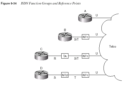
Table 8-44 lists the function groups and reference points shown in Figure 8-34.
Table 8-45 summarizes these types of permanent connections and lists some of the strengths
and weaknesses.
Table 8-44
Figure 8-34 Function Groups and Reference Point SummaryRouter Function Group(s)
Connected to Reference
Point(s)
A TE1, NT1 U
B TE1 S/T (combined S and T)
C TE2 R
D TE1 S
Table 8-45
Comparison of Leased Versus Packet SwitchingType of WAN
Service
Data Link
Protocols Strengths and Weaknesses
Leased Offers pervasive availability. Can be expensive for long
circuits. Is more expensive for providers to engineer than are
packet services.
PPP Can improve speed of routing protocol convergence. Allows
multivendor interoperability. Offers error recovery option.
continues
602
Chapter 8: WAN Protocols and DesignFigure 8-35 outlines the process of Frame Relay initialization.
HDLC Is the IOS default. Requires a Cisco router on each end.
LAPB Provides error recovery, but this also can result in throttling
(slowing) the data rate.
Packet Switched Allows addition of new sites to be made quickly. Typically
involves a lower cost.
Frame Relay Allows bursting past CIR, giving perception of free capacity.
Is pervasive in the United States.
ATM As a WAN technology, is not as pervasively available as
Frame Relay. Offers built-in Quality of Service as its most
attractive feature.
X.25 Is available pervasively in some parts of the world. Error
recovery features are beneficial when links have higher error
rates. Typically is the third choice of these three if all are
available to all connected sites.
Table 8-45
Comparison of Leased Versus Packet Switching (Continued)Type of WAN
Service
Data Link
Protocols Strengths and Weaknesses
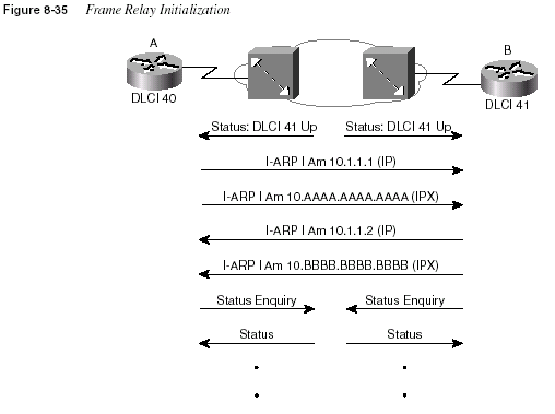
Foundation Summary
603Figure 8-36 lists the main Cisco router product families.
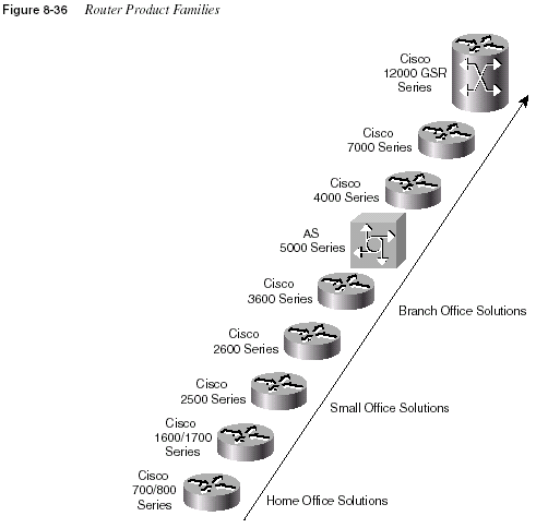
Figure 8-37 provides a conceptual diagram of the two forms of Frame Relay encapsulation.
Because the frames flow from DTE to DTE, both DTEs must agree to the encapsulation used
.However, each VC can use a different encapsulation.
604
Chapter 8: WAN Protocols and Design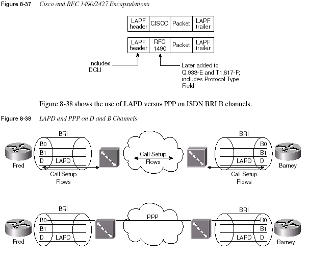
Q&A
605Q&A
As mentioned in Chapter 1, “All About the Cisco Certified Network Associate Certification,”
the questions and scenarios in this book are more difficult than what you should experience on
the actual exam. The questions do not attempt to cover more breadth or depth than the exam;
however, they are designed to make sure that you know the answer. Rather than allowing you
to derive the answer from clues hidden inside the question itself, the questions challenge your
understanding and recall of the subject. Questions from the “Do I Know This Already?” quiz
from the beginning of the chapter are repeated here to ensure that you have mastered the
chapter’s topic areas. Hopefully, these questions will help limit the number of exam questions
on which you narrow your choices to two options and then guess.
The answers to these questions can be found in Appendix A, on page 768.
1
Name two WAN data link protocols for which the standards define a protocol type field,which is used to define the type of header that follows the WAN data link header.
2
Name two WAN data link protocols that define a method of announcing the Layer 3addresses of the interface to other devices attached to the WAN.
3
What does the acronym LAPD stand for? Is it used as the Layer 2 protocol on dialed ISDNbearer channels? If not, what is used?
4
“Frame Relay uses source and destination DLCIs in the Frame Relay header, with length10, 11, or 12 bits.” Which parts of this statement do you agree with? Which parts do you
disagree with? Why?
5
Explain the purpose of Inverse ARP. Explain how Inverse ARP uses Frame Relaybroadcasts.
6
Would a Frame Relay switch connected to a router behave differently if the IETF optionwere deleted from the
encapsulation frame-relay ietf command on that attached router?Would a router on the other end of the VC behave any differently if the same change were
made?
7
What does NBMA stand for? Does it apply to PPP links? What about X.25 networks orFrame Relay networks?
8
Define the terms DCE and DTE in the context of the physical layer and a point-to-pointserial link.
9
What layer of OSI is most closely related to the functions of Frame Relay? Why?10
When Inverse ARP is used by default, what additional configuration is needed to get IGRProuting updates to flow over each VC?
11
Define the attributes of a partial-mesh and full-mesh Frame Relay network.12
What key pieces of information are required in the frame-relay map statement?606
Chapter 8: WAN Protocols and Design13
When creating a partial-mesh Frame Relay network, are you required to usesubinterfaces?
14
What benefit related to routing protocols can be gained by using subinterfaces with apartial mesh?
15
Can PPP perform dynamic assignment of IP addresses? If so, is the feature alwaysenabled?
16
Create a configuration to enable PPP on serial 0 for IP and IPX. Make up IP and IPX Layer3 addresses as needed.
17
Create a configuration for Router1 that has Frame Relay VCs to Router2 and Router3(DLCIs 202 and 203, respectively) for Frame Relay on Router1’s serial 1 interface. Use
any IP and IPX addresses you like. Assume that the network is not fully meshed.
18
What show command will tell you the time that a PVC became active? How does therouter know what time the PVC became active?
19
What show commands list Frame Relay information about mapping? In what instanceswill the information displayed include the Layer 3 addresses of other routers?
20
True or false: The no keepalive command on a Frame Relay serial interface causes nofurther Cisco proprietary keepalive messages to be sent to the Frame Relay switch.
21
What debug options will show Inverse ARP messages?22
True or false: The Frame Relay map configuration command allows more than one Layer3 protocol address mapping on the same configuration command.
23
What do the letters in ISDN represent? What about BRI and PRI?24
Define the term function group. List two examples of function groups.25
Define the term reference point. List two examples of reference points.26
How many bearer channels are in a BRI? What about a PRI in North America? What abouta PRI in Europe?
27
True or false: ISDN defines protocols that can be functionally equivalent to OSI Layers 1,2, and 3. Defend your answer.
28
What reference points are used by ISDN BRI interfaces on Cisco routers?29
What do the letters LAPD represent? Is LAPD used on ISDN channels? If so, which ones?30
Name the standards body that defines ISDN protocols.31
What ISDN functions do standards ITU-T Q.920 and Q.930 define? Does either standardcorrelate to an OSI layer?
32
What ISDN functions does standard ITU-T I.430 define? Does it correlate to an OSIlayer?
Q&A
60733
What do the letters SPID represent, and what does the term mean?34
Define the terms TE1, TE2, and TA. Which term(s) imply that one of the other two mustbe in use?
35
What reference point is used between the customer premise and the phone company inNorth America? What about in Europe?
36
Define the term SBus, and give one example of when it would be useful.37
What data link (OSI Layer 2) protocols are valid on an ISDN B channel?38
Define the terms PAP and CHAP. Which one(s) send the passwords in clear text format?39
Define MLPPP. Describe the typical home or small office use of MLPPP.40
CHAP configuration uses names and passwords. Given Routers A and B, describe whatnames and passwords must match in the respective CHAP configurations.
41
Configure ISDN interface BRI1, assuming that it is attached to a DMS-100 ISDN switch,that it uses only one SPID of 404555121201, and that you want to screen calls so that only
calls from 404555999901 are accepted.
42
Name the configuration command used to enable FRF.9 compression on a point-to-pointFrame Relay subinterface.
43
List the types of compression that are available on PPP links.44
Describe the decision process performed by the IOS to attempt to dial a connection usinglegacy DDR.
45
If packets from 10.1.1.0/24 were “interesting” in relation to DDR configuration, such thatpackets from 10.1.1.0/24 caused a DDR connection out an interface BRI0, list the
configuration commands that would make the IOS think that those packets were
interesting on BRI0.
46
List the typical EIA/TIA standard interfaces used for serial cables with a Cisco router.47
What field has Cisco added to the HDLC header, making it proprietary?608
Chapter 8: WAN Protocols and DesignScenarios
Scenario 8-1: Point-to-Point Verification
Use Example 8-33, Example 8-34, and Example 8-35 when completing the exercises and
answering the questions that follow.
Example 8-33
Albuquerque Command Output, Scenario 8-1Albuquerque#
show ip interface briefInterface IP-Address OK? Method Status Protocol
Serial0 199.1.1.129 YES NVRAM up up
Serial1 199.1.1.193 YES NVRAM up up
Ethernet0 199.1.1.33 YES NVRAM up up
Albuquerque#
show ip routeCodes: C - connected, S - static, I - IGRP, R - RIP, M - mobile, B - BGP
D - EIGRP, EX - EIGRP external, O - OSPF, IA - OSPF inter area
N1 - OSPF NSSA external type 1, N2 - OSPF NSSA external type 2
E1 - OSPF external type 1, E2 - OSPF external type 2, E - EGP
i - IS-IS, L1 - IS-IS level-1, L2 - IS-IS level-2, * - candidate default
U - per-user static route, o - ODR
Gateway of last resort is not set
199.1.1.0/24 is variably subnetted, 7 subnets, 2 masks
C 199.1.1.192/27 is directly connected, Serial1
C 199.1.1.130/32 is directly connected, Serial0
C 199.1.1.128/27 is directly connected, Serial0
I 199.1.1.160/27 [100/10476] via 199.1.1.130, 00:00:01, Serial0
[100/10476] via 199.1.1.194, 00:00:54, Serial1
I 199.1.1.64/27 [100/8539] via 199.1.1.130, 00:00:01, Serial0
I 199.1.1.96/27 [100/8539] via 199.1.1.194, 00:00:54, Serial1
C 199.1.1.32/27 is directly connected, Ethernet0
Albuquerque#
show ipx routeCodes: C - Connected primary network, c - Connected secondary network
S - Static, F - Floating static, L - Local (internal), W - IPXWAN
R - RIP, E - EIGRP, N - NLSP, X - External, A - Aggregate
s - seconds, u - uses
6 Total IPX routes. Up to 1 parallel paths and 16 hops allowed.
No default route known.
C 1001 (SAP), E0
C 2001 (PPP), Se0
C 2003 (HDLC), Se1
R 1002 [07/01] via 2001.0200.bbbb.bbbb, 50s, Se0
R 1003 [07/01] via 2003.0200.cccc.cccc, 57s, Se1
R 2002 [07/01] via 2001.0200.bbbb.bbbb, 51s, Se0
Scenario 8-1: Point-to-Point Verification
609Albuquerque#
debug ppp negotiationPPP protocol negotiation debugging is on
%LINK-3-UPDOWN: Interface Serial0, changed state to up
Se0 PPP: Treating connection as a dedicated line
Se0 PPP: Phase is ESTABLISHING, Active Open
Se0 LCP: O CONFREQ [Closed] id 15 len 10
Se0 LCP: MagicNumber 0x003C2A1F (0x0506003C2A1F)
Se0 LCP: I CONFREQ [REQsent] id 34 len 10
Se0 LCP: MagicNumber 0x0648CFD3 (0x05060648CFD3)
Se0 LCP: O CONFACK [REQsent] id 34 len 10
Se0 LCP: MagicNumber 0x0648CFD3 (0x05060648CFD3)
Se0 LCP: TIMEout: Time = 0xBA0E0 State = ACKsent
Se0 LCP: O CONFREQ [ACKsent] id 16 len 10
Se0 LCP: MagicNumber 0x003C2A1F (0x0506003C2A1F)
Se0 LCP: I CONFACK [ACKsent] id 16 len 10
Se0 LCP: MagicNumber 0x003C2A1F (0x0506003C2A1F)
Se0 LCP: State is Open
Se0 PPP: Phase is UP
Se0 IPCP: O CONFREQ [Closed] id 3 len 10
Se0 IPCP: Address 199.1.1.129 (0x0306C7010181)
Se0 CDPCP: O CONFREQ [Closed] id 3 len 4
Se0 LLC2CP: O CONFREQ [Closed] id 3 len 4
Se0 IPXCP: O CONFREQ [Closed] id 3 len 18
Se0 IPXCP: Network 0x00002001 (0x010600002001)
Se0 IPXCP: Node 0200.aaaa.aaaa (0x02080200AAAAAAAA)
Se0 IPCP: I CONFREQ [REQsent] id 4 len 10
Se0 IPCP: Address 199.1.1.130 (0x0306C7010182)
Se0 IPCP: O CONFACK [REQsent] id 4 len 10
Se0 IPCP: Address 199.1.1.130 (0x0306C7010182)
Se0 CDPCP: I CONFREQ [REQsent] id 6 len 4
Se0 CDPCP: O CONFACK [REQsent] id 6 len 4
Se0 LLC2CP: I CONFREQ [REQsent] id 6 len 4
Se0 LLC2CP: O CONFACK [REQsent] id 6 len 4
Se0 IPXCP: I CONFREQ [REQsent] id 4 len 18
Se0 IPXCP: Network 0x00002001 (0x010600002001)
Se0 IPXCP: Node 0200.bbbb.bbbb (0x02080200BBBBBBBB)
Se0 IPXCP: O CONFACK [REQsent] id 4 len 18
Se0 IPXCP: Network 0x00002001 (0x010600002001)
Se0 IPXCP: Node 0200.bbbb.bbbb (0x02080200BBBBBBBB)
Example 8-34
Yosemite Command Output, Scenario 8-1Yosemite#
show ipx interface briefInterface IPX Network Encapsulation Status IPX State
Serial0 2001 PPP up [up]
Serial1 2002 LAPB up [up]
Ethernet0 1002 SAP up [up]
Yosemite#
show ipx routeCodes: C - Connected primary network, c - Connected secondary network
Example 8-33
Albuquerque Command Output, Scenario 8-1 (Continued)continues
610
Chapter 8: WAN Protocols and DesignS - Static, F - Floating static, L - Local (internal), W - IPXWAN
R - RIP, E - EIGRP, N - NLSP, X - External, A - Aggregate
s - seconds, u - uses
6 Total IPX routes. Up to 1 parallel paths and 16 hops allowed.
No default route known.
C 1002 (SAP), E0
C 2001 (PPP), Se0
C 2002 (LAPB), Se1
R 1001 [07/01] via 2001.0200.aaaa.aaaa, 46s, Se0
R 1003 [13/02] via 2001.0200.aaaa.aaaa, 47s, Se0
R 2003 [07/01] via 2001.0200.aaaa.aaaa, 47s, Se0
Yosemite#
show interface serial 1 accountingSerial1
Protocol Pkts In Chars In Pkts Out Chars Out
IP 37 2798 41 3106
Yosemite#
ping ipx 2002.0200.cccc.ccccType escape sequence to abort.
Sending 5, 100-byte IPX Cisco Echoes to 2002.0200.cccc.cccc, timeout is 2 seconds:
.....
Success rate is 0 percent (0/5)
Yosemite#
ping 199.1.1.162Type escape sequence to abort.
Sending 5, 100-byte ICMP Echos to 199.1.1.162, timeout is 2 seconds:
!!!!!
Success rate is 100 percent (5/5), round-trip min/avg/max = 8/8/8 ms
Yosemite#
ping ipx 1003.0000.30ac.70efType escape sequence to abort.
Sending 5, 100-byte IPX Cisco Echoes to 1003.0000.30ac.70ef, timeout is 2 seconds:
!!!!!
Success rate is 100 percent (5/5), round-trip min/avg/max = 8/8/12 ms
Example 8-35
Seville Command Output, Scenario 8-1Seville#
show ip routeCodes: C - connected, S - static, I - IGRP, R - RIP, M - mobile, B - BGP
D - EIGRP, EX - EIGRP external, O - OSPF, IA - OSPF inter area
N1 - OSPF NSSA external type 1, N2 - OSPF NSSA external type 2
E1 - OSPF external type 1, E2 - OSPF external type 2, E - EGP
i - IS-IS, L1 - IS-IS level-1, L2 - IS-IS level-2, * - candidate default
U - per-user static route, o - ODR
Gateway of last resort is not set
Example 8-34
Yosemite Command Output, Scenario 8-1 (Continued)Scenario 8-1: Point-to-Point Verification
611199.1.1.0/27 is subnetted, 6 subnets
C 199.1.1.192 is directly connected, Serial0
I 199.1.1.128 [100/10476] via 199.1.1.161, 00:00:36, Serial1
[100/10476] via 199.1.1.193, 00:01:09, Serial0
C 199.1.1.160 is directly connected, Serial1
I 199.1.1.64 [100/8539] via 199.1.1.161, 00:00:36, Serial1
C 199.1.1.96 is directly connected, Ethernet0
I 199.1.1.32 [100/8539] via 199.1.1.193, 00:01:09, Serial0
Seville#
show ipx routeCodes: C - Connected primary network, c - Connected secondary network
S - Static, F - Floating static, L - Local (internal), W - IPXWAN
R - RIP, E - EIGRP, N - NLSP, X - External, A - Aggregate
s - seconds, u - uses
6 Total IPX routes. Up to 1 parallel paths and 16 hops allowed.
No default route known.
C 1003 (SAP), E0
C 2002 (LAPB), Se1
C 2003 (HDLC), Se0
R 1001 [07/01] via 2003.0200.aaaa.aaaa, 2s, Se0
R 1002 [13/02] via 2003.0200.aaaa.aaaa, 2s, Se0
R 2001 [07/01] via 2003.0200.aaaa.aaaa, 2s, Se0
Seville#
show interface serial 0 accountingSerial0
Protocol Pkts In Chars In Pkts Out Chars Out
IP 44 3482 40 3512
IPX 46 3478 44 2710
CDP 21 6531 26 7694
Seville#
debug lapbLAPB link debugging is on
%LINK-3-UPDOWN: Interface Serial1, changed state to up
Serial1: LAPB O SABMSENT (2) SABM P
Serial1: LAPB I SABMSENT (2) UA F
Serial1: LAPB I CONNECT (104) IFRAME 0 0
Serial1: LAPB O CONNECT (76) IFRAME 0 1Serial1: LAPB I CONNECT (76) IFRAME 1 1
Serial1: LAPB O CONNECT (2) RR (R) 2
Seville#
Seville#
ping 199.1.1.161Type escape sequence to abort.
Sending 5, 100-byte ICMP Echos to 199.1.1.161, timeout is 2 seconds:
!!!!!
Success rate is 100 percent (5/5), round-trip min/avg/max = 8/8/12 ms
Seville#
Example 8-35
Seville Command Output, Scenario 8-1 (Continued)continues
612
Chapter 8: WAN Protocols and DesignAssuming the details established in Example 8-33 through Example 8-35 for Scenario 8-1,
complete or answer the following:
1
Create a diagram for the network.2
Complete Table 8-47.3
Why are there seven IP routes in Albuquerque and Yosemite, and only six in Seville?Scenario 8-2: Frame Relay Verification
Use Example 8-36, Example 8-37, Example 8-38, and Example 8-39 when completing the
exercises and answering the questions that follow.
Serial1: LAPB O CONNECT (102) IFRAME 1 3
Serial1: LAPB I CONNECT (102) IFRAME 3 2
Serial1: LAPB O CONNECT (2) RR (R) 4
Serial1: LAPB O CONNECT (102) IFRAME 2 4
Serial1: LAPB I CONNECT (102) IFRAME 4 3
Serial1: LAPB O CONNECT (2) RR (R) 5
Serial1: LAPB O CONNECT (102) IFRAME 3 5
Serial1: LAPB I CONNECT (2) RR (R) 4
Serial1: LAPB I CONNECT (102) IFRAME 5 4
Serial1: LAPB O CONNECT (2) RR (R) 6
Serial1: LAPB O CONNECT (102) IFRAME 4 6
Serial1: LAPB I CONNECT (102) IFRAME 6 5
Serial1: LAPB O CONNECT (2) RR (R) 7
Serial1: LAPB O CONNECT (102) IFRAME 5 7
Serial1: LAPB I CONNECT (102) IFRAME 7 6
Serial1: LAPB O CONNECT (2) RR (R) 0
Table 8-47
Layer 3 Addresses on the PPP Serial LinksRouter Serial Port Encapsulation IP Address IPX Address
Albuquerque s0
Albuquerque s1
Yosemite s0
Yosemite s1
Seville s0
Seville s1
Example 8-35
Seville Command Output, Scenario 8-1 (Continued)Scenario 8-2: Frame Relay Verification
613Example 8-36
Atlanta Command Output, Scenario 8-2Atlanta#
show interface s 0Serial0 is up, line protocol is up
Hardware is HD64570
MTU 1500 bytes, BW 1544 Kbit, DLY 20000 usec, rely 255/255, load 1/255
Encapsulation FRAME-RELAY, loopback not set, keepalive set (10 sec)
LMI enq sent 32, LMI stat recvd 32, LMI upd recvd 0, DTE LMI up
LMI enq recvd 0, LMI stat sent 0, LMI upd sent 0
LMI DLCI 1023 LMI type is CISCO frame relay DTE
Broadcast queue 0/64, broadcasts sent/dropped 75/0, interface broadcasts 59
Last input 00:00:00, output 00:00:07, output hang never
Last clearing of “show interface” counters never
Queuing strategy: fifo
Output queue 0/40, 0 drops; input queue 0/75, 0 drops
5 minute input rate 0 bits/sec, 0 packets/sec
5 minute output rate 0 bits/sec, 0 packets/sec
74 packets input, 5697 bytes, 0 no buffer
Received 32 broadcasts, 0 runts, 0 giants, 0 throttles
0 input errors, 0 CRC, 0 frame, 0 overrun, 0 ignored, 0 abort
110 packets output, 9438 bytes, 0 underruns
0 output errors, 0 collisions, 2 interface resets
0 output buffer failures, 0 output buffers swapped out
0 carrier transitions
DCD=up DSR=up DTR=up RTS=up CTS=up
Atlanta#
show interface s 0.1Serial0.1 is up, line protocol is up
Hardware is HD64570
Internet address is 168.10.202.1/24
MTU 1500 bytes, BW 1544 Kbit, DLY 20000 usec, rely 255/255, load 1/255
Encapsulation FRAME-RELAY
Atlanta#
show interface s 0.2Serial0.2 is up, line protocol is up
Hardware is HD64570
Internet address is 168.10.203.1/24
MTU 1500 bytes, BW 1544 Kbit, DLY 20000 usec, rely 255/255, load 1/255
Encapsulation FRAME-RELAY
Atlanta#
show interface s 0.3Serial0.3 is up, line protocol is up
Hardware is HD64570
Internet address is 168.10.204.1/24
MTU 1500 bytes, BW 1544 Kbit, DLY 20000 usec, rely 255/255, load 1/255
Encapsulation FRAME-RELAY
Atlanta#
show frame-relay mapSerial0.3 (up): point-to-point dlci, dlci 54(0x36,0xC60), broadcast, IETF
status defined, active
Serial0.2 (up): point-to-point dlci, dlci 53(0x35,0xC50), broadcast
status defined, active
Serial0.1 (up): point-to-point dlci, dlci 52(0x34,0xC40), broadcast
status defined, active
continues
614
Chapter 8: WAN Protocols and DesignAtlanta#
show frame-relay lmiLMI Statistics for interface Serial0 (Frame Relay DTE) LMI TYPE = CISCO
Invalid Unnumbered info 0 Invalid Prot Disc 0
Invalid dummy Call Ref 0 Invalid Msg Type 0
Invalid Status Message 0 Invalid Lock Shift 0
Invalid Information ID 0 Invalid Report IE Len 0
Invalid Report Request 0 Invalid Keep IE Len 0
Num Status Enq. Sent 43 Num Status msgs Rcvd 43
Num Update Status Rcvd 0 Num Status Timeouts 0
Atlanta#
debug frame-relay eventsFrame Relay events debugging is on
Atlanta#
configure terminalEnter configuration commands, one per line. End with Ctrl-Z.
Atlanta(config)#
interface serial 0Atlanta(config-if)#
shutdown%LINEPROTO-5-UPDOWN: Line protocol on Interface Serial0.1, changed state to down
%LINEPROTO-5-UPDOWN: Line protocol on Interface Serial0.2, changed state to down
%LINEPROTO-5-UPDOWN: Line protocol on Interface Serial0.3, changed state to down
%LINEPROTO-5-UPDOWN: Line protocol on Interface Serial0, changed state to down
%LINK-5-CHANGED: Interface Serial0, changed state to administratively down
%FR-5-DLCICHANGE: Interface Serial0 - DLCI 54 state changed to DELETED
%FR-5-DLCICHANGE: Interface Serial0 - DLCI 53 state changed to DELETED
%FR-5-DLCICHANGE: Interface Serial0 - DLCI 52 state changed to DELETED
Atlanta(config-if)#
no shutdownAtlanta(config-if)#
^Z%LINEPROTO-5-UPDOWN: Line protocol on Interface Serial0.1, changed state to up
%FR-5-DLCICHANGE: Interface Serial0 - DLCI 52 state changed to ACTIVE
%LINEPROTO-5-UPDOWN: Line protocol on Interface Serial0.2, changed state to up
%FR-5-DLCICHANGE: Interface Serial0 - DLCI 53 state changed to ACTIVE
%LINEPROTO-5-UPDOWN: Line protocol on Interface Serial0.3, changed state to up
%FR-5-DLCICHANGE: Interface Serial0 - DLCI 54 state changed to ACTIVE
%SYS-5-CONFIG_I: Configured from console by console
%LINEPROTO-5-UPDOWN: Line protocol on Interface Serial0, changed state to up
%LINK-3-UPDOWN: Interface Serial0, changed state to up
Atlanta#
show frame mapSerial0.3 (up): point-to-point dlci, dlci 54(0x36,0xC60), broadcast, IETF
status defined, active
Serial0.2 (up): point-to-point dlci, dlci 53(0x35,0xC50), broadcast
status defined, active
Serial0.1 (up): point-to-point dlci, dlci 52(0x34,0xC40), broadcast
status defined, active
Atlanta#
debug frame-relay lmiFrame Relay LMI debugging is on
Displaying all Frame Relay LMI data
Atlanta#
Example 8-36
Atlanta Command Output, Scenario 8-2 (Continued)Scenario 8-2: Frame Relay Verification
615Serial0(out): StEnq, myseq 6, yourseen 5, DTE up
datagramstart = 0x45B25C, datagramsize = 13
FR encap = 0xFCF10309
00 75 01 01 01 03 02 06 05
Serial0(in): Status, myseq 6
RT IE 1, length 1, type 1
KA IE 3, length 2, yourseq 6 , myseq 6
Example 8-37
Charlotte Command Output, Scenario 8-2Charlotte#
show interface s 0.1Serial0.1 is up, line protocol is up
Hardware is HD64570
Internet address is 168.10.202.2/24
MTU 1500 bytes, BW 1544 Kbit, DLY 20000 usec, rely 255/255, load 1/255
Encapsulation FRAME-RELAY
Charlotte#
show cdp neighbor detail-------------------------
Device ID: Atlanta
Entry address(es):
IP address: 168.10.202.1
Novell address: 202.0200.aaaa.aaaa
Platform: Cisco 2500, Capabilities: Router
Interface: Serial0.1, Port ID (outgoing port): Serial0.1
Holdtime : 164 sec
Version :
Cisco Internetwork Operating System Software
IOS (tm) 2500 Software (C2500-AINR-L), Version 11.2(11), RELEASE SOFTWARE (fc1)
Copyright 1986-1997 by Cisco Systems, Inc.
Compiled Mon 29-Dec-97 18:47 by ckralik
Charlotte#
show frame-relay mapSerial0.1 (up): point-to-point dlci, dlci 51(0x33,0xC30), broadcast
status defined, active
Charlotte#
show frame-relay pvcPVC Statistics for interface Serial0 (Frame Relay DTE)
DLCI = 51, DLCI USAGE = LOCAL, PVC STATUS = ACTIVE, INTERFACE = Serial0.1
input pkts 36 output pkts 28 in bytes 4506
out bytes 2862 dropped pkts 1 in FECN pkts 0
in BECN pkts 0 out FECN pkts 0 out BECN pkts 0
in DE pkts 0 out DE pkts 0
out bcast pkts 26 out bcast bytes 2774
pvc create time 00:08:54, last time pvc status changed 00:01:26
Charlotte#
show frame-relay lmiExample 8-36
Atlanta Command Output, Scenario 8-2 (Continued)continues
616
Chapter 8: WAN Protocols and DesignLMI Statistics for interface Serial0 (Frame Relay DTE) LMI TYPE = CCITT
Invalid Unnumbered info 0 Invalid Prot Disc 0
Invalid dummy Call Ref 0 Invalid Msg Type 0
Invalid Status Message 0 Invalid Lock Shift 0
Invalid Information ID 0 Invalid Report IE Len 0
Invalid Report Request 0 Invalid Keep IE Len 0
Num Status Enq. Sent 54 Num Status msgs Rcvd 37
Num Update Status Rcvd 0 Num Status Timeouts 17
Example 8-38
Nashville Command Output, Scenario 8-2Nashville#
show cdp neighbor detail-------------------------
Device ID: Atlanta
Entry address(es):
IP address: 168.10.203.1
Novell address: 203.0200.aaaa.aaaa
Platform: Cisco 2500, Capabilities: Router
Interface: Serial0.1, Port ID (outgoing port): Serial0.2
Holdtime : 139 sec
Version :
Cisco Internetwork Operating System Software
IOS (tm) 2500 Software (C2500-AINR-L), Version 11.2(11), RELEASE SOFTWARE (fc1)
Copyright 1986-1997 by Cisco Systems, Inc.
Compiled Mon 29-Dec-97 18:47 by ckralik
Nashville#
show frame-relay pvcPVC Statistics for interface Serial0 (Frame Relay DTE)
DLCI = 51, DLCI USAGE = LOCAL, PVC STATUS = ACTIVE, INTERFACE = Serial0.1
input pkts 52 output pkts 47 in bytes 6784
out bytes 6143 dropped pkts 0 in FECN pkts 0
in BECN pkts 0 out FECN pkts 0 out BECN pkts 0
in DE pkts 0 out DE pkts 0
out bcast pkts 46 out bcast bytes 6099
pvc create time 00:13:50, last time pvc status changed 00:06:51
Nashville#
show frame-relay trafficFrame Relay statistics:
ARP requests sent 0, ARP replies sent 0
ARP requests recvd 0, ARP replies recvd 0
Nashville#
show frame-relay lmiLMI Statistics for interface Serial0 (Frame Relay DTE) LMI TYPE = CISCO
Invalid Unnumbered info 0 Invalid Prot Disc 0
Invalid dummy Call Ref 0 Invalid Msg Type 0
Invalid Status Message 0 Invalid Lock Shift 0
Example 8-37
Charlotte Command Output, Scenario 8-2 (Continued)Scenario 8-2: Frame Relay Verification
617Invalid Information ID 0 Invalid Report IE Len 0
Invalid Report Request 0 Invalid Keep IE Len 0
Num Status Enq. Sent 84 Num Status msgs Rcvd 84
Num Update Status Rcvd 0 Num Status Timeouts 0
Example 8-39
Boston Command Output, Scenario 8-2Boston#
show interface s 0.1Serial0.1 is up, line protocol is up
Hardware is HD64570
Internet address is 168.10.204.4/24
MTU 1500 bytes, BW 1544 Kbit, DLY 20000 usec, rely 255/255, load 1/255
Encapsulation FRAME-RELAY
Boston#
show cdp neighbor detail-------------------------
Device ID: Atlanta
Entry address(es):
IP address: 168.10.204.1
Novell address: 204.0200.aaaa.aaaa
Platform: Cisco 2500, Capabilities: Router
Interface: Serial0.1, Port ID (outgoing port): Serial0.3
Holdtime : 125 sec
Version :
Cisco Internetwork Operating System Software
IOS (tm) 2500 Software (C2500-AINR-L), Version 11.2(11), RELEASE SOFTWARE (fc1)
Copyright 1986-1997 by Cisco Systems, Inc.
Compiled Mon 29-Dec-97 18:47 by ckralik
Boston#
show frame-relay mapSerial0.1 (up): point-to-point dlci, dlci 51(0x33,0xC30), broadcast, IETF
status defined, active
Boston#
show frame-relay pvcPVC Statistics for interface Serial0 (Frame Relay DTE)
DLCI = 51, DLCI USAGE = LOCAL, PVC STATUS = ACTIVE, INTERFACE = Serial0.1
input pkts 65 output pkts 54 in bytes 8475
out bytes 6906 dropped pkts 1 in FECN pkts 0
in BECN pkts 0 out FECN pkts 0 out BECN pkts 0
in DE pkts 0 out DE pkts 0
out bcast pkts 52 out bcast bytes 6792
pvc create time 00:15:43, last time pvc status changed 00:07:54
Num Update Status Rcvd 0 Num Status Timeouts 0
Example 8-38
Nashville Command Output, Scenario 8-2 (Continued)618
Chapter 8: WAN Protocols and DesignAssuming the details established in Example 8-36 through Example 8-39 for Scenario 8-2,
complete or answer the following:
1
Create a diagram for the network based on the command output in Example 8-36 throughExample 8-39.
2
Complete Table 8-48 with the Layer 3 addresses on the serial links.3
Complete Table 8-49 with LMI types and encapsulations used.Table 8-48
Layer 3 Addresses in Scenario 8-2Router Port Subinterface IP Address IPX Address
Atlanta s0
Atlanta s0
Atlanta s0
Atlanta s0
Charlotte s0
Charlotte s0
Nashville s0
Nashville s0
Boston s0
Boston s0
Table 8-49
LMI and Encapsulations Used in Scenario 8-2Router Port Subinterface LMI Type Encapsulation
Atlanta s0
Atlanta s0
Atlanta s0
Atlanta s0
Charlotte s0
Charlotte s0
Nashville s0
Nashville s0
Boston s0
Boston s0
Scenario 8-3: Point-to-Point Configuration
619Scenario 8-3: Point-to-Point Configuration
Your job is to deploy a new network for an environmental research firm. Two main research
sites are in Boston and Atlanta; a T/1 line has been ordered between those two sites. The field
site in Alaska will need occasional access; ISDN BRI will be used. Another field site in the rain
forest of Podunk has a digital 56kbps link, but it has bursts of errors because parts of the line
are microwave.
The design criteria are listed following Figure 8-39, which shows the routers and links. Note
that some design criteria are contrived to force you to configure different features; these are
designated with an asterisk (*).
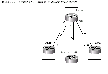
The design criteria are as follows:
•
Use three different WAN data link protocols.*•
ISDN BRI will be used between Boston and Alaska. Boston’s phone number is1115551111; Alaska’s is 2225552222.
•
Both ISDN BRIs are attached to DMS-100 switches.•
Use IP subnets and IPX networks in Table 8-50. Allocate addresses as needed.•
All IP user traffic is considered interesting for DDR.•
IPX RIP and IP IGRP are the routing protocols of choice.620
Chapter 8: WAN Protocols and DesignAssuming the design criteria previously listed and the information in Table 8-50 for Scenario
8-3, complete or answer the following:
1
Create configurations for all four routers.2
Defend your choices for the different data link protocols.3
Name all methods that Boston is using in your configuration to learn the Layer 3 addresseson the other end of each link.
Scenario 8-4: Frame Relay Configuration
Your job is to deploy a new network. Site A is the main site, with PVC connections to the other
four sites. Sites D and E also have a PVC between them. Examine Figure 8-40 and perform the
activities that follow.
Table 8-50
Scenario 8-3 Chart of Layer 3 Groups for the Network in Figure 8-23Data Link IP Subnet IPX Network
Boston Ethernet 200.1.1.0/24 101
Podunk Ethernet 200.1.2.0/24 102
Atlanta Ethernet 200.1.3.0/24 103
Alaska Ethernet 200.1.4.0/24 104
Boston-Podunk 200.1.5.4/30 202
Boston-Atlanta 200.1.5.8/30 203
Boston-Alaska 200.1.5.12/30 204
Scenario 8-4: Frame Relay Configuration
621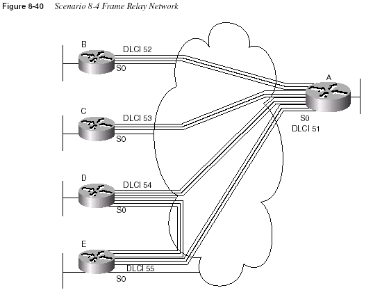
1
Plan the IP and IPX addresses to be used. Use Table 8-51 if helpful. Use IP network168.15.0.0.
2
Using the DLCIs in Figure 8-40, create configurations for Routers A, B, and E. Usemultipoint subinterfaces for the VCs between A, D, and E.
3
Create alternate configurations for Router A and Router E using point-to-pointsubinterfaces instead of multipoint.
4
Describe the contents of the IP and IPX routing tables on Router A, assuming that thenetwork created from the preceding task is working properly. Only LAN-based IP subnets
and IPX networks need to be listed for this exercise. Use Table 8-51 and Table 8-52 if
useful.
622
Chapter 8: WAN Protocols and DesignTable 8-51
Scenario 8-4 Layer 3 Address Planning ChartInterface Subinterface IP Address IPX Address
A’s Ethernet
B’s Ethernet
C’s Ethernet
D’s Ethernet
E’s Ethernet
A’s S0
A’s S0
A’s S0
A’s S0
A’s S0
B’s S0
C’s S0
D’s S0
D’s S0
E’s S0
E’s S0
Table 8-52
Scenario 8-4: IP and IPX Routing Table ContentsLayer 3 Group Outgoing Interface
Next-Hop IP
Address, or
Connected
Next-Hop IPX
Address, or
Connected
Scenario 8-5: Frame Relay Configuration Dissection
623Scenario 8-5: Frame Relay Configuration Dissection
A four-router Frame Relay network has been configured. Consider the configurations in
Example 8-40, Example 8-41, Example 8-42, and Example 8-43, and answer the questions that
follow.
Example 8-40
Scenario 8-5, Router 1 ConfigurationHostname Router1
!
ipx routing 0200.1111.1111
!
interface serial0
encapsulation frame-relay
!
interface serial 0.1
ip address 180.1.1.1 255.255.255.0
ipx network AAA1801
frame-relay interface-dlci 501
!
interface serial 0.2
ip address 180.1.2.1 255.255.255.0
ipx network AAA1802
frame-relay interface-dlci 502
!
interface serial 0.1
ip address 180.1.3.1 255.255.255.0
ipx network AAA1803
frame-relay interface-dlci 503
!
interface ethernet 0
ip address 180.1.10.1 255.255.255.0
ipx network AAA18010
!
router igrp 1
network 180.1.0.0
Example 8-41
Scenario 8-5, Router 2 ConfigurationHostname Router2
!
ipx routing 0200.2222.2222
!
interface serial0
encapsulation frame-relay
!
interface serial 0.1
ip address 180.1.1.2 255.255.255.0
ipx network AAA1801
frame-relay interface-dlci 500
!
interface ethernet 0
continues
624
Chapter 8: WAN Protocols and Designip address 180.1.11.2 255.255.255.0
ipx network AAA18011
!
router igrp 1
network 180.1.0.0
Example 8-42
Scenario 8-5, Router 3 ConfigurationHostname Router3
!
ipx routing 0200.3333.3333
!
interface serial0
encapsulation frame-relay
!
interface serial 0.1
ip address 180.1.2.3 255.255.255.0
ipx network AAA1802
frame-relay interface-dlci 500
!
interface ethernet 0
ip address 180.1.12.3 255.255.255.0
ipx network AAA18012
!
router igrp 1
network 180.1.0.0
Example 8-43
Scenario 8-5, Router 4 ConfigurationHostname router4
!
ipx routing 0200.4444.4444
!
interface serial0
encapsulation frame-relay
!
interface serial 0.1
ip address 180.1.3.4 255.255.255.0
ipx network AAA1803
frame-relay interface-dlci 500
!
interface ethernet 0
ip address 180.1.13.4 255.255.255.0
ipx network AAA18013
!
router igrp 1
network 180.1.0.0
Example 8-41
Scenario 8-5, Router 2 Configuration (Continued)Scenario 8-5: Frame Relay Configuration Dissection
625Assuming the details established in Example 8-40 through Example 8-43 for Scenario 8-5,
complete or answer the following:
1
Draw a diagram of the network.2
Is IGRP split horizon on or off? How can you tell?3
What type of Frame Relay encapsulation is used?4
Create the commands on Router 1 and Router 2 to disable Inverse ARP and instead usestatic mapping.
626
Chapter 8: WAN Protocols and DesignAnswers to Scenarios
Answers to Scenario 8-1: Point-to-Point Verification
Figure 8-41 is a diagram that matches the configuration.
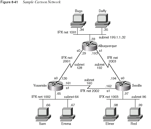
The IP and IPX addresses used on the various router interfaces were one of the tasks for this
scenario. Table 8-53 is a completed version of Table 8-47, which was the blank table in which
you recorded your answers for this task. Finding all the IP and IPX addresses in Examples
8-33, 8-34, and 8-35 requires some persistence. The best plan of attack is to find all IP addresses
and masks that you can, then find all IPX network numbers, and finally decide which addresses
are in the same IP subnet and IPX network.
The full IPX addresses are a little more difficult to find. The best method with the commands
shown is via the
show ipx interface brief command and the show ipx route command. Inparticular, the routing table lists the full IPX addresses, not just the network numbers.
Answers to Scenario 8-2: Frame Relay Verification
627The encapsulations are not easy to notice from the commands listed. The
show interfacecommand would have simply listed the answer. However, in this case, a few subtle reminders
were included. The
debug output on Albuquerque and Seville shows PPP output onAlbuquerque’s S0 interface and LAPB output for Seville’s S1 interface. The
show ipx routecommands also happen to list the encapsulation for connected networks. Table 8-53
summarizes the details.
An extra IP route is included in the routing tables on the PPP-connected routers. When the IPCP
announces the IP addresses on each end of the link, the IOS decides to add a host route
specifically to that IP address. For example, Albuquerque has a route to 199.1.1.128/27 (subnet
on serial link to Yosemite) and to 199.1.1.130/32 (Yosemite’s address on that same link). The
/32 signifies that the route is a host route.
Answers to Scenario 8-2: Frame Relay Verification
Figure 8-42 is a diagram that matches the configuration.
Discovering the IP addresses and subinterfaces is relatively straightforward. The
showcommands for most subinterfaces are provided, and these list the IP address and mask used. The
show cdp neighbor detail
commands also mentioned the IP address of the connected routers.The full IPX addresses were more challenging to deduce. The only command that listed the IPX
addresses was the
show cdp neighbor detail command, which was used in Examples 8-37,8-38, and 8-39. The
show frame-relay map command should seemingly have provided thatinformation, but because all the subinterfaces are point-to-point, no true mapping is needed.
The subinterface acts like a point-to-point link, so the neighboring router’s IPX address is
not shown in the
show frame-relay map command output. A debug frame-relay eventscommand, which shows output for Inverse ARP flows, could have identified the IPX addresses,
but Inverse ARP is not enabled on point-to-point subinterfaces because it is not needed.
In short, there was no way to deduce all IPX addresses from the scenario.
Table 8-53
Scenario 8-1 Layer 3 Addresses on the Point-to-Point Serial Links—Completed TableRouter Serial Port Encapsulation IP Address IPX Address
Albuquerque s0 PPP 199.1.1.129 2001.0200.aaaa.aaaa
Albuquerque s1 HDLC 199.1.1.193 2003.0200.aaaa.aaaa
Yosemite s0 PPP 199.1.1.130 2001.0200.bbbb.bbbb
Yosemite s1 LAPB 199.1.1.161 2002.0200.bbbb.bbbb
Seville s0 HDLC 199.1.1.194 2003.0200.cccc.cccc
Seville s1 LAPB 199.1.1.162 2002.0200.cccc.cccc
628
Chapter 8: WAN Protocols and Design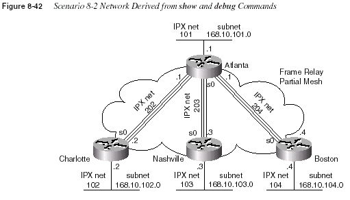
Table 8-54 lists the answers for Layer 3 addresses and subinterface numbers (Table 8-48, in the
scenario description).
Note:
There was not enough information to derive the IPX addresses for Charlotte, Nashville, and Boston. The IPXnetwork numbers are implied by the
show cdp neighbor detail command output.Table 8-54
Layer 3 Addresses in Scenario 8-2—Completed TableRouter Port Subinterface IP Address IPX Address
Atlanta s0 1 168.10.202.1 202.0200.AAAA.AAAA
Atlanta s0 2 168.10.203.1 203.0200.AAAA.AAAA
Atlanta s0 3 168.10.204.1 204.0200.AAAA.AAAA
Atlanta s0
Charlotte s0 1 168.10.202.2 202.????.????.????
Charlotte s0
Nashville s0 1 168.10.203.3 203. ????.????.????
Nashville s0
Boston s0 1 168.10.204.4 204. ????.????.????
Boston s0
Answers to Scenario 8-3: Point-to-Point Configuration
629The LMI type was discovered only by examining the output of the
show frame-relay lmicommand. However, this command does not list whether the LMI type was learned via
autosensing or whether it was configured.
The encapsulation type is much more obscure. The
show frame-relay map command outputholds the answer. Table 8-55 summarizes those answers (Table 8-49, in the scenario
description).
Answers to Scenario 8-3: Point-to-Point Configuration
Example 8-44, Example 8-45, Example 8-46, and Example 8-47 show the configurations.
Table 8-55
Scenario 8-2 LMI and Encapsulations Used—Completed TableRouter Port Subinterface LMI Type Encapsulation
Atlanta s0 — Cisco
Atlanta s0 1 cisco
Atlanta s0 2 cisco
Atlanta s0 3 ietf
Charlotte s0 — Q933A
Charlotte s0 1 cisco
Nashville s0 — Cisco
Nashville s0 1 cisco
Boston s0 — Cisco
Boston s0 1 ietf
Example 8-44
Boston Configuration for Scenario 8-3, Point-to-Point Configurationhostname Boston
ipx routing 0200.aaaa.aaaa
no ip domain-lookup
username Alaska password Larry
isdn switch-type basic-dms100
!
interface serial0
encapsulation multi-lapb-dce
ip address 200.1.5.5 255.255.255.252
ipx network 202
!
interface serial1
encapsulation hdlc
ip address 200.1.5.9 255.255.255.252
ipx network 203
!
continues
630
Chapter 8: WAN Protocols and Designinterface bri0
encapsulation ppp
isdn spid1 1115551111
ip address 200.1.5.13 255.255.255.252
ipx network 204
ppp authentication chap
!
interface ethernet 0
ip address 200.1.1.1 255.255.255.0
ipx network 101
!
router igrp 1
network 200.1.1.0
network 200.1.5.0
Example 8-45
Podunk Configuration for Scenario 8-3, Point-to-Point Configurationhostname Podunk
ipx routing 0200.bbbb.bbbb
no ip domain-lookup
!
interface serial0
encapsulation multi-lapb
ip address 200.1.5.6 255.255.255.252
ipx network 202
!
interface ethernet 0
ip address 200.1.2.1 255.255.255.0
ipx network 102
!
router igrp 1
network 200.1.2.0
network 200.1.5.0
Example 8-46
Atlanta Configuration for Scenario 8-3, Point-to-Point Configurationhostname Atlanta
ipx routing 0200.cccc.cccc
no ip domain-lookup
!
interface serial0
encapsulation hdlc
ip address 200.1.5.10 255.255.255.252
ipx network 203
!
interface ethernet 0
ip address 200.1.3.1 255.255.255.0
ipx network 103
!
router igrp 1
network 200.1.3.0
network 200.1.5.0
Example 8-44
Boston Configuration for Scenario 8-3, Point-to-Point Configuration (Continued)Answers to Scenario 8-4: Frame Relay Configuration
631The choices for serial encapsulation in this solution are HDLC, PPP, and LAPB. PPP was
chosen on the ISDN B channel because it provides CHAP authentication. LAPB is used on the
link with known continuing high error rates so that LAPB can recover data lost going across the
link. Because the problem statement also requests three different encapsulations, HDLC was
chosen.
As you progress through your certifications, Cisco will try to ask questions that force you to
deduce a fact from a limited amount of information. The final question in this scenario requires
that you think beyond the topic of serial encapsulations. PPP control protocols are used by
Boston on the PPP link to discern the Layer 3 addresses on the other end of the link. However,
LAPB and HDLC do not perform this function. CDP is enabled on each of these links by default
and is sending messages to discover information about Boston’s neighbors. Also, Boston
examines the source address of routing updates to learn the Layer 3 addresses of its neighbors.
Answers to Scenario 8-4: Frame Relay Configuration
Check your IP and IPX address design against the ones chosen in Table 8-56. Of course, your
choices most likely are different. However, you should have one subnet per VC when using only
point-to-point subinterfaces. With the original criteria of Routers A, D, and E each using
Example 8-47
Alaska Configuration for Scenario 8-3, Frame Relay Configurationhostname Alaska
no ip domain-lookup
ipx routing 0200.dddd.dddd
!
isdn switch-type basic-dms100
username Boston password Larry
!
interface BRI 0
encapsulation ppp
ip address 200.1.5.14 255.255.255.252
ipx network 204
isdn spid1 22255522220
ppp authentication chap
!
dialer-group 1
dialer idle-timeout 120
dialer map ip 200.1.5.13 name Boston 11115551111
!
interface ethernet 0
ip address 200.1.4.1 255.255.255.0
ipx network 104
!
router igrp 1
network 200.1.4.0
network 200.1.5.0
!
dialer-list 1 protocol ip permit
632
Chapter 8: WAN Protocols and Designmultipoint subinterfaces, those three subinterfaces should have been in the same IP subnet and
IPX network. Table 8-35 gives the planned Layer 3 addresses for the configurations using
multipoint among those three routers.
Assuming the DLCIs in Figure 8-40, Example 8-48, Example 8-49, and Example 8-50, show
the configurations for Routers A, B, and E, respectively, using multipoint subinterfaces for the
VCs between A, D, and E.
Table 8-56
Scenario 8-4 Layer 3 Address Planning Chart, Multipoint A-D-EInterface Subinterface IP Address IPX Address
A’s Ethernet 168.15.101.1 101.0200.AAAA.AAAA
B’s Ethernet 168.15.102.1 102.0200.BBBB.BBBB
C’s Ethernet 168.15.103.1 103.0200.CCCC.CCCC
D’s Ethernet 168.15.104.1 104.0200.DDDD.DDDD
E’s Ethernet 168.15.105.1 105.0200.EEEE.EEEE
A’s S0 2 168.15.202.1 202.0200.AAAA.AAAA
A’s S0 3 168.15.203.1 203.0200.AAAA.AAAA
A’s S0 1 168.15.200.1 200.0200.AAAA.AAAA
B’s S0 2 168.15.202.2 202.0200.BBBB.BBBB
C’s S0 3 168.15.203.3 203.0200.CCCC.CCCC
D’s S0 1 168.15.200.4 200.0200.DDDD.DDDD
E’s S0 1 168.15.200.5 200.0200.EEEE.EEEE
Example 8-48
Router A Configuration, Scenario 8-4ipx routing 0200.aaaa.aaaa
!
interface serial0
encapsulation frame-relay
!
interface serial 0.1 multipoint
ip address 168.15.200.1 255.255.255.0
ipx network 200
frame-relay interface-dlci 54
frame-relay interface-dlci 55
!
interface serial 0.2 point-to-point
ip address 168.15.202.1 255.255.255.0
ipx network 202
interface-dlci 52
!
interface serial 0.3 point-to-point
ip address 168.15.203.1 255.255.255.0
ipx network 203
Answers to Scenario 8-4: Frame Relay Configuration
633interface-dlci 53
!
!
interface ethernet 0
ip address 168.15.101.1 255.255.255.0
ipx network 101
!
router igrp 1
network 168.15.0.0
Example 8-49
Router B Configuration, Scenario 8-4ipx routing 0200.bbbb.bbbb
!
interface serial0
encapsulation frame-relay
!
interface serial 0.2 point-to-point
ip address 168.15.202.2 255.255.255.0
ipx network 202
frame-relay interface-dlci 51
!
interface ethernet 0
ip address 168.15.102.1 255.255.255.0
ipx network 102
!
router igrp 1
network 168.15.0.0
Example 8-50
Router E Configuration, Scenario 8-4ipx routing 0200.eeee.eeee
!
interface serial0
encapsulation frame-relay
!
interface serial 0.1 multipoint
ip address 168.15.200.5 255.255.255.0
ipx network 200
frame-relay interface-dlci 51
frame-relay interface-dlci 54
!
interface ethernet 0
ip address 168.15.105.1 255.255.255.0
ipx network 105
!
router igrp 1
network 168.15.0.0
Example 8-48
Router A Configuration, Scenario 8-4 (Continued)634
Chapter 8: WAN Protocols and DesignMultipoint subinterfaces will work perfectly well in this topology. Using multipoint also
conserves IP subnets, as seen in the next task in this scenario. When changing strategy to use
only point-to-point subinterfaces, each of the three VCs in the triangle of Routers A, D, and E
will require a different subnet and IPX network number. Table 8-57 shows the choices made
here. Example 8-51 and Example 8-52 show alternate configurations for Router A and Router
E using point-to-point instead of multipoint subinterfaces.
Table 8-57
Scenario 8-4 Layer 3 Address Planning Chart, All Point-to-Point SubinterfacesInterface Subinterface IP Address IPX Address
A’s Ethernet 168.15.101.1 101.0200.AAAA.AAAA
B’s Ethernet 168.15.102.1 102.0200.BBBB.BBBB
C’s Ethernet 168.15.103.1 103.0200.CCCC.CCCC
D’s Ethernet 168.15.104.1 104.0200.DDDD.DDDD
E’s Ethernet 168.15.105.1 105.0200.EEEE.EEEE
A’s S0 2 168.15.202.1 202.0200.AAAA.AAAA
A’s S0 3 168.15.203.1 203.0200.AAAA.AAAA
A’s S0 4 168.15.204.1 204.0200.AAAA.AAAA
A’s S0 5 168.15.205.1 205.0200.AAAA.AAAA
B’s S0 2 168.15.202.2 202.0200.BBBB.BBBB
C’s S0 3 168.15.203.3 203.0200.CCCC.CCCC
D’s S0 4 168.15.204.4 204.0200.DDDD.DDDD
D’s S0 1 168.15.190.4 190.0200.DDDD.DDDD
E’s S0 5 168.15.205.5 205.0200.EEEE.EEEE
E’s S0 1 168.15.190.5 190.0200.EEEE.EEEE
Example 8-51
Router A Configuration, Scenario 8-4, All Point-to-Point Subinterfacesipx routing 0200.aaaa.aaaa
!
interface serial0
encapsulation frame-relay
!
interface serial 0.2 point-to-point
ip address 168.15.202.1 255.255.255.0
ipx network 202
frame-relay interface-dlci 52
!
interface serial 0.3 point-to-point
ip address 168.15.203.1 255.255.255.0
ipx network 203
frame-relay interface-dlci 53
Answers to Scenario 8-4: Frame Relay Configuration
635The contents of the IP and IPX routing tables asked for in Step 4 of this scenario will be
provided in shorthand in Table 8-58. The third byte of the IP address is shown in the Layer 3
group column because the third byte (octet) fully comprises the subnet field. Not coincidentally,
the IPX network number was chosen as the same number, mainly to make network operation
easier.
!
interface serial 0.4 point-to-point
ip address 168.15.204.1 255.255.255.0
ipx network 204
frame-relay interface-dlci 54
!
interface serial 0.5 point-to-point
ip address 168.15.205.1 255.255.255.0
ipx network 205
frame-relay interface-dlci 55
!
interface ethernet 0
ip address 168.15.101.1 255.255.255.0
ipx network 101
!
router igrp 1
network 168.15.0.0
Example 8-52
Router E Configuration, Scenario 8-4, Subinterfacesipx routing 0200.eeee.eeee
!
interface serial0
encapsulation frame-relay
!
interface serial 0.1 point-to-point
ip address 168.15.190.5 255.255.255.0
ipx network 190
interface-dlci 54
!
interface serial 0.5 point-to-point
ip address 168.15.200.5 255.255.255.0
ipx network 200
interface-dlci 51
!
interface ethernet 0
ip address 168.15.105.1 255.255.255.0
ipx network 105
!
router igrp 1
network 168.15.0.0
Example 8-51
Router A Configuration, Scenario 8-4, All Point-to-Point Subinterfaces (Continued)636
Chapter 8: WAN Protocols and DesignAnswers to Scenario 8-5: Frame Relay Configuration
Dissection
Figure 8-43 supplies the network diagram described in Scenario 8-5. The subinterfaces are all
point-to-point, which is a clue that each VC has a subnet and IPX network associated with it.
An examination of the IP addresses or IPX network numbers should have been enough to
deduce which routers are attached to each end of each VC.
Table 8-58
Scenario 8-4 IP and IPX Routing Table Contents, Router ALayer 3 Group Outgoing Interface
Next-Hop IP
Address, or
Connected
Next-Hop IPX
Address, or
Connected
101 E0 Connected Connected
102 S0.2 168.15.202.2 202.0200.bbbb.bbbb
103 S0.3 168.15.203.3 203.0200.cccc.cccc
104 S0.4 168.15.204.4 204.0200.dddd.dddd
105 S0.5 168.15.205.5 205.0200.eeee.eeee
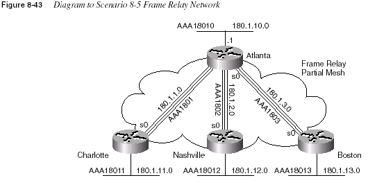
Split horizon is turned off on all interfaces because that is the default with point-to-point
subinterfaces and because no command has been configured to turn it on.
Cisco encapsulation was used in each case. The
encapsulation frame-relay command defaultsto the use of Cisco encapsulation.
Answers to Scenario 8-5: Frame Relay Configuration Dissection
637Disabling Inverse ARP is unlikely in real networks. However, this exercise was added so that
you can be ready for the exam. Example 8-53 and Example 8-54 show the commands used to
migrate to not using Inverse ARP. The maps are necessary for both IP and IPX because both
need to be routed across the Frame Relay network.
The
interface-dlci settings are no longer needed because the IOS can deduce which DLCI isused by the subinterface based on the
map command.Example 8-53
Scenario 8-5, Atlanta Router—Changes for Static MappingAtlanta(config)#
interface serial 0.1Atlanta(config-subif)#
no frame-relay interface-dlci 501Atlanta(config-subif)#
frame-relay map ip 180.1.1.2 501 broadcastAtlanta(config-subif)#
frame-relay map ipx aaa1801.0200.2222.2222 501 broadcastAtlanta(config-subif)#
interface serial 0.2Atlanta(config-subif)#
no frame-relay interface-dlci 502Atlanta(config-subif)#
frame-relay map ip 180.1.2.3 502 broadcastAtlanta(config-subif)#
frame-relay map ipx aaa1802.0200.3333.3333 502 broadcastAtlanta(config-subif)#
interface serial 0.3Atlanta(config-subif)#
no frame-relay interface-dlci 503Atlanta(config-subif)#
frame-relay map ip 180.1.3.4 503 broadcastAtlanta(config-subif)#
frame-relay map ipx aaa1803.0200.4444.4444 503 broadcastExample 8-54
Scenario 8-5, Charlotte Router—Changes for Static MappingCharlotte(config)#
interface serial 0.1Charlotte(config-subif)#
no frame-relay interface-dlci 500Charlotte(config-subif)#
frame-relay map ip 180.1.1.1 500 broadcastCharlotte(config-subif)#
frame-relay map ipx aaa1801.0200.1111.1111 500 broadcast