This chapter covers the following topics that you will need to master as a CCNA:
•
TCP/IP Protocols
The TCP/IP protocol suite is very important in networks today.
This section covers several portions of the protocol suite, including TCP, UDP, ARP,
ICMP, FTP, and TFTP.
•
IP Addressing and Subnetting
IP addressing is absolutely the most important
topic on the CCNA exam. This section takes a detailed look at IP addressing and
outlines five different types of questions the CCNA exam uses to test your knowledge.
•
IP Configuration
This section covers the configuration commands required for IP
addressing and name resolution on a Cisco router.
•
IPX Addressing and Routing
The Novell NetWare protocol suite is the other
major protocol suite covered in detail on the CCNA exam. This section covers IPX
addressing and routing and also discusses the concepts and parameters used for the
varied IPX encapsulation options.
•
IPX Configuration
This section covers the IOS commands used for configuration
of IPX features.
C
H
A
P
T
E
R
5
Network Protocols
TCP/IP is the most important protocol covered on the CCNA exam and is the protocol used
most often in networks today. This chapter covers the TCP/IP protocols as well as IP
addressing and subnetting. Cisco expects CCNAs not just to know IP addressing and
routing, but also to know the concepts behind many other TCP/IP protocols. In addition,
CCNAs should be able to easily recall the commands used to examine the details of IP
processing in a router. Of course, Cisco also requires you to continually prove your
understanding of IP subnetting on the CCNA exam and on almost all other Cisco exams.
This chapter also covers Novell’s NetWare protocols. NetWare protocols have been well
established and widely implemented for more than a decade. Very few changes that affect
the router’s role in forwarding NetWare traffic have been made in the last four years.
Routing is straightforward; if you understand IP routing, then you likely will find IPX
routing easy to grasp. Of course, this book also assumes that you have completed the ICND
course or have logged equivalent experience, so the text is written under the assumption that
NetWare protocols are not new to you. This chapter briefly reviews the main concepts,
clarifies the trickiest details, and helps you refine your retention and recall with questions
and scenarios.
How to Best Use This Chapter
By taking the following steps, you can make better use of your study time:
•
Keep your notes and the answers for all your work with this book in one place, for
easy reference.
•
Take the “Do I Know This Already?” quiz, and write down your answers. Studies
show that retention is significantly increased through writing down facts and
concepts, even if you never look at the information again.
•
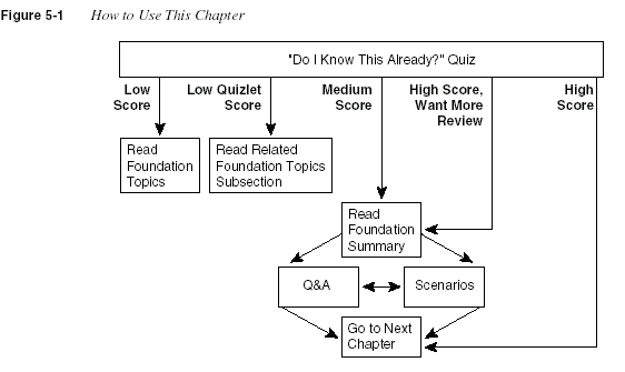
Use the diagram in Figure 5-1 to guide you to the next step.
212
Chapter 5: Network Protocols

“Do I Know This Already?” Quiz
The purpose of the “Do I Know This Already?” quiz is to help you decide what parts of this
chapter to use. If you already intend to read the entire chapter, you do not necessarily need to
answer these questions now.
This 16-question quiz helps you determine how to spend your limited study time. The quiz is
sectioned into four smaller four-question “quizlets,” which correspond to the four major
headings in the chapter. Figure 5-1 outlines suggestions on how to spend your time in this
chapter. Use Table 5-1 to record your score.
Table 5-1
Scoresheet for Quiz and Quizlets
Quizlet
Number
Foundation Topics Section Covering
These Questions Questions Score
1 TCP/IP Protocols 1 to 4
2 IP Addressing and Subnetting 5 to 8
3 IP Configuration 9 to 12
4 IPX Addressing and Routing
IPX Configuration
13 to 16
All questions 1 to 16
“Do I Know This Already?” Quiz
213
1
What do TCP, UDP, IP, and ICMP stand for? Which protocol is considered to be
Layer 3-equivalent when comparing TCP/IP to the OSI protocols?
___________________________________________________________________
___________________________________________________________________
___________________________________________________________________
2
Describe how TCP performs error recovery. What role do the routers play?
___________________________________________________________________
___________________________________________________________________
___________________________________________________________________
3
Does FTP or TFTP perform error recovery? If so, describe the basics of how error
recovery is performed.
___________________________________________________________________
___________________________________________________________________
___________________________________________________________________
4
How many TCP segments are exchanged to establish a TCP connection? How many
are required to terminate a TCP connection?
___________________________________________________________________
___________________________________________________________________
___________________________________________________________________
5
Given the IP address 134.141.7.11 and the mask 255.255.255.0, what is the subnet
number?
___________________________________________________________________
___________________________________________________________________
___________________________________________________________________
214
Chapter 5: Network Protocols
6
Given the IP address 134.141.7.11 and the mask 255.255.255.0, what is the subnet
broadcast address?
__________________________________________________________________
__________________________________________________________________
__________________________________________________________________
7
Given the IP address 200.1.1.130 and the mask 255.255.255.224, what are the
assignable IP addresses in this subnet?
__________________________________________________________________
__________________________________________________________________
__________________________________________________________________
8
Given the IP address 220.8.7.100 and the mask 255.255.255.240, what are all the
subnet numbers if the same (static) mask is used for all subnets in this network?
__________________________________________________________________
__________________________________________________________________
__________________________________________________________________
9
Create a minimal configuration enabling IP on each interface on a 2501 router (two
serial, one Ethernet). The NIC assigned you network 8.0.0.0. Your boss says that you
need, at most, 200 hosts per subnet. You decide against using VLSM. Your boss says
to plan your subnets so that you can have as many subnets as possible, rather than
allow for larger subnets later. You decide to start with the lowest numerical values for
the subnet number you will use. Assume that point-to-point serial links will be
attached to this router and that RIP is the routing protocol.
__________________________________________________________________
__________________________________________________________________
__________________________________________________________________
10
Describe the question and possible responses in setup mode when a router wants to
know the mask used on an interface. How can the router derive the correct mask
from the information supplied by the user?
__________________________________________________________________
__________________________________________________________________
__________________________________________________________________
“Do I Know This Already?” Quiz
215
11
Define the purpose of the
trace
command. What type of messages does it send, and
what type of ICMP messages does it receive?
___________________________________________________________________
___________________________________________________________________
___________________________________________________________________
12
What causes the output from an IOS
ping
command to display “UUUUU?”
___________________________________________________________________
___________________________________________________________________
___________________________________________________________________
13
How many bytes comprise an IPX address?
___________________________________________________________________
___________________________________________________________________
___________________________________________________________________
14
Give an example of an IPX network mask used when subnetting.
___________________________________________________________________
___________________________________________________________________
___________________________________________________________________
15
Create a configuration enabling IPX on each interface, with RIP and SAP enabled
on each as well, for a 2501 (two serial, one Ethernet) router. Use networks 100, 200,
and 300 for interfaces S0, S1, and E0, respectively. Choose any node values.
___________________________________________________________________
___________________________________________________________________
___________________________________________________________________
16
What
show
command lists the IPX address(es) of interfaces in a Cisco router?
___________________________________________________________________
___________________________________________________________________
___________________________________________________________________
216
Chapter 5: Network Protocols
The answers to this quiz are found in Appendix A, “Answers to the ‘Do I Know This Already?’
Quizzes and Q&A Sections,” on page 724. The suggested choices for your next step are as
follows:
•
8 or less overall score
—Read the entire chapter. This includes the “Foundation Topics”
and “Foundation Summary” sections, the Q&A section, and the scenarios at the end of the
chapter.
•
2 or less on any quizlet
—Review the subsection(s) of the “Foundation Topics” part of
this chapter, based on Table 5-1. Then move into the “Foundation Summary” section, the
Q&A section, and the scenarios at the end of the chapter.
•
9 to 12 overall score
—Begin with the “Foundation Summary” section, and then go to the
Q&A section and the scenarios at the end of the chapter.
•
13 or more overall score
—If you want more review on these topics, skip to the
“Foundation Summary” section, and then go to the Q&A section and the scenarios at the
end of the chapter. Otherwise, move to the next chapter.
TCP/IP Protocols
217
Foundation Topics
TCP/IP Protocols
CCNAs work with multiple protocols on a daily basis; none of these is more important than
TCP/IP. This section examines the TCP, UDP, ICMP, and ARP protocols in detail. TCP and
UDP are the two transport layer (Layer 4) protocols most often used by applications in a
TCP/IP network. ICMP and ARP are actually parts of the network layer (Layer 3) of TCP/IP
and are used in conjunction with IP. As you’ll see on the exam, IP addressing is something that
all CCNAs must master to confidently pass the exam. Due to the importance of IP, IP addressing
will be covered in great detail in the next section of this chapter.
Transmission Control Protocol
One common feature of routing is to discard packets for a variety of reasons. For instance, no
route might match the packet, or there may not be enough buffer space in the router to store
the packet until the next link is available. Layer 3 protocols do not typically provide for
retransmission; a typical commentary is, “That’s done by some higher-layer protocol.”
To pass the CCNA exam, you must understand how one popular “higher-layer” protocol does
error recovery—namely, the Transmission Control Protocol (TCP). Defined in RFC 793, TCP
performs error recovery as well as other features, including these:
•
Data transfer
•
Multiplexing
•
Error recovery (reliability)
•
Flow control using windowing
•
Connection establishment and termination
TCP accomplishes these goals via mechanisms at the endpoint computers. TCP relies on IP for
end-to-end deliveries of the data, including routing issues. In other words, TCP performs only
part of the functions necessary to deliver the data between applications.
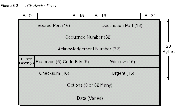
Figure 5-2 shows the fields in the TCP header. Not all the fields will be described in this text,
but several fields will be referred to in this section. The Internetworking Technologies
Multimedia (ITM) CD, which is a suggested prerequisite for the exam, lists the fields with a
brief explanation, as does the Cisco Press book on which ITM is based:
Internetworking
Technologies Handbook
.
218
Chapter 5: Network Protocols
Ordered Data Transfer
As with other functions in any protocol stack, TCP provides service for the next-higher layer.
The TCP/IP protocol stack has only four layers, so TCP’s next-higher layer is the application
layer. Therefore, TCP data transfer implies delivering data from one application to another.
(The TCP/IP application layer performs functions similar to the upper three layers of the OSI
model.) Applications use TCP services by issuing programmatic calls to TCP, supplying the
data to be sent, the destination IP address, and a port number that identifies the application that
should receive the data. The port number, along with the destination IP address and the name
of the transport layer protocol (TCP), form a socket.
TCP accomplishes data transfer by establishing a connection between a socket on each of the
endpoint computers.
Applications use TCP services by opening a socket; TCP manages the
delivery of the data to the other socket.
A socket source/destination pair uniquely identifies a
relationship between two applications in a network. TCP manages the ordered transfer of data
between these two sockets, using IP services to deliver the data.
Multiplexing
In this context, multiplexing refers to the choices made upon receipt of data. TCP’s
multiplexing task is to decide which application layer process to give the data to, after the data
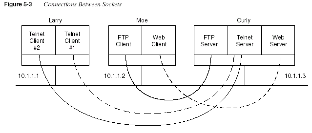
is received. For example, in Figure 5-3, Larry is a multiuser system in which two users have
TCP/IP Protocols
219
telnetted to Curly. The socket used by the Telnet server on Curly consists of an IP address, the
transport layer protocol in use, and a port number—in this case, 10.1.1.3, TCP, 23. Because data
coming from both Telnet clients is sent to that socket, Curly cannot distinguish which client has
sent data to the Telnet server based on only Curly’s socket. For the Telnet server to know which
connection the data is coming over, the combination of the socket at the server and the socket
at the client is used to uniquely identify connection. For example, Client 1 uses socket 10.1.1.1,
TCP, 1027; Client 2 uses socket 10.1.1.1, TCP, 1028. Now Curly can distinguish between the
two clients. So, TCP uses the socket connection between the two sockets to perform
multiplexing.
Port numbers are a vital part of the socket concept. Well-known port numbers are used by
servers; other port numbers are used by clients. Applications that provide a service, such as FTP,
Telnet, and Web servers, open a socket using a well-known port and listen for connection
requests. Because these connection requests from clients are required to include both the source
and the destination port numbers, the port numbers used by the servers must be well known.
Therefore, each server has a hard-coded well-known port number, as defined in the well-known
numbers RFC. On client machines, where the requests originate, any unused port number can
be allocated. The result is that each client on the same host uses a different port number, but a
server uses the same port number for all connections. For example, 100 Telnet clients on the
same host would each use a different port number, but the Telnet server, with 100 clients
connected to it, would have only one socket and therefore only one port number. The
combination of source and destination sockets allows all participating hosts to distinguish
the source and destination of the data. (Look to www.rfc-editor.org to find RFCs such as
the well-known numbers RFC 1700.)
220
Chapter 5: Network Protocols
Table 5-2 summarizes the socket connections as shown in Figure 5-3.
In this context, multiplexing is defined as the process of choosing which application receives
the data after it is received by lower-layer protocols. Consider that definition with the four
socket connections in Table 5-2, for packets destined to the server (Curly). All destination
socket information is for 10.1.1.3, with TCP, but the use of different port numbers allows Curly
to choose the correct service to which to pass the data. Also notice that the port numbers do not
have to be unique. The FTP client on Moe and the Telnet Client 1 on Larry both use port 1027,
but their sockets are unique because each uses a different IP address. Also, when the Telnet
servers send data back to Clients 1 and 2, Larry knows how to multiplex to the correct client
application because each uses a unique port number on Larry.
Error Recovery (Reliability)
Reliable data transfer is one of the most important and most typically remembered features
of TCP. To accomplish reliability, data bytes are numbered using the sequence and acknowledgment
fields in the TCP header. TCP achieves reliability in both directions, using the
sequence number field of one direction combined with the acknowledgment field in the
opposite direction. Figure 5-4 shows the basic operation.
Table 5-2
TCP Connections from Figure 5-3
Connection Client Socket Server Socket
Telnet client 1 to server (10.1.1.1, TCP, 1027) (10.1.1.3, TCP, 23)
Telnet client 2 to server (10.1.1.1, TCP, 1028) (10.1.1.3, TCP, 23)
FTP client to FTP server (10.1.1.2, TCP, 1027) (10.1.1.3, TCP, 21)
Web client to Web server (10.1.1.2, TCP, 1029) (10.1.1.3, TCP, 80)
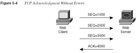
In Figure 5-4, the acknowledgment field in the TCP header sent by the Web server implies the
next byte to be received; this is called
forward acknowledgment
. The sequence number reflects
the number of the first byte in the segment. In this case, each TCP segment is 1000 bytes in
length; the sequence and acknowledgment fields count the number of bytes.
TCP/IP Protocols
221
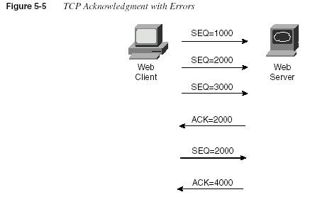
Figure 5-5 depicts the same scenario, but the second TCP segment was lost or in error. The Web
server’s reply has an ACK field equal to 2000, implying that the Web server is expecting byte
number 2000 next. The TCP function at the Web client could then recover lost data by resending
the second TCP segment. The TCP protocol allows for resending just that segment and then
waits, hoping that the Web server will reply with an acknowledgment that equals 4000. TCP
also allows the resending host to begin with a segment in error and resend all TCP segments.
Flow Control Using Windowing
TCP implements flow control by taking advantage of the sequence and acknowledgment fields
in the TCP header, along with another field called the
window
field. This window field implies
the maximum number of unacknowledged bytes outstanding at any instant in time. The window
starts small and then grows until errors occur. The window then “slides” up and down based on
network performance. When the window is full, the sender will not send, which controls the
flow of data. Figure 5-6 shows windowing, with a current window size of 3000. Each TCP
segment has 1000 bytes of data.
Notice that the Web client must wait after sending the third segment because the window is
exhausted. When the acknowledgment has been received, another window can be sent. Because
there have been no errors, the Web server grants a larger window to the client, so now 4000
bytes can be sent before an acknowledgment is received by the client. In other words, the
window field is used by the receiver to tell the sender how much data it can send before the next
acknowledgment. As with other TCP features, windowing is symmetrical—both sides send and
receive, and in each case the receiver grants a window to the sender using the window field.
222
Chapter 5: Network Protocols
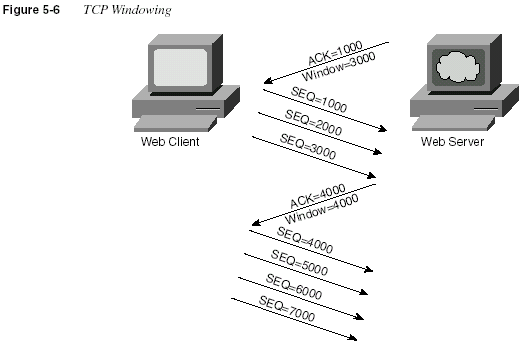
Windowing does not require that the sender stop sending in all cases, as is shown in Figure
5-6. If an acknowledgment is received before the window is exhausted, the sender continues to
send data until the current window is exhausted. With no errors or congestion, the sender can
send continually after the initially small window has been increased.
Connection Establishment and Termination
Connection establishment is the last TCP function reviewed in this section, but it occurs before
any of the other TCP features can begin their work. Connection establishment refers to the
process of initializing sequence and acknowledgment fields and agreeing to the port numbers
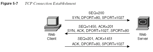
used. Figure 5-7 shows an example of connection establishment flow.
TCP/IP Protocols
223
This three-way connection establishment flow must complete before data transfer can begin.
The connection exists between the two sockets, although there is no single socket field in the
TCP header. Of the three parts of a socket, the IP addresses are implied based on the source and
destination IP addresses in the IP header. TCP is implied because a TCP header is in use, as
implied by the protocol field value in the IP header. Therefore, the only parts of the socket that
need to be encoded in the TCP header are the port numbers.
Two single-bit portions of the flags field of the TCP header are used to signal the three-step
process for connection establishment. Called the SYN and ACK flags, these bits have a
particularly interesting meaning. SYN means, “Synchronize the sequence numbers,” which is
one necessary component in initialization for TCP. The ACK field means “the acknowledgment
field is valid in this header.” Until the sequence numbers are initialized, the acknowledgment
field cannot be very useful. Also notice that in the initial flow in Figure 5-7, no acknowledgment
number is shown—this is because that number is not valid yet. Because the ACK field must be
present in all the ensuing segments, the ACK bit will continue to be set until the connection is
terminated.
The sequence and acknowledgment number fields are initialized to any number that fits into
the 4-byte fields; the actual values shown in Figure 5-7 are simply example values. The
initialization flows are each considered to have a single byte of data, as reflected in the
acknowledgment number fields in the example.
Figure 5-8 shows TCP connection termination.
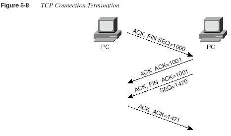
This four-way termination sequence is straightforward and uses an additional flag, called the
FIN bit. (FIN is short for “finished,” as you might guess.) One interesting note: Before the
device receiving the first FIN segment sends the third flow in the sequence, TCP notifies the
application that the connection is coming down. TCP waits on an acknowledgment from the
application before sending the segment. That’s why the second flow is required: To
224
Chapter 5: Network Protocolsacknowledge the first so that the side taking down the connection doesn’t start resending the
first TCP segment.
TCP Function Summary
Table 5-3 summarizes TCP functions.
User Datagram Protocol
The CCNA exam requires that you be able to compare and contrast the User Datagram Protocol
(UDP) with TCP. UDP was designed to provide a service for applications in which messages
could be exchanged. Unlike TCP, UDP provides no reliability, no windowing, and no function
to ensure that the data is received in the order in which it was sent. However, UDP provides
some functions of TCP, such as data transfer and multiplexing, and it does so with fewer bytes
of overhead in the UDP header.
UDP multiplexes use port numbers in an identical fashion to TCP. The only difference in UDP
(compared to TCP) sockets is that instead of designating TCP as the transport protocol, the
transport protocol is UDP. An application could open identical port numbers on the same host
but use TCP in one case and UDP in the other. This is not typical but certainly is allowed.
Servers that allow use of TCP and UDP reserve the use of the same port number for each, as
shown in the assigned numbers RFC (currently RFC 1700—www.isi.edu/in-notes/rfc1700.txt).
UDP data transfer differs from TCP in that no reordering or recovery is accomplished.
Applications using UDP are tolerant of the lost data, or they have some application mechanism
to recover lost data. For example, Domain Name System (DNS) requests use UDP because the
user will retry an operation if the DNS resolution fails. The Network File System (NFS)
performs recovery with application layer code, so UDP features are acceptable to NFS.
Table 5-3
TCP Function SummaryFunction Description
Data transfer Continuous stream of ordered data.
Multiplexing Function that allows receiving hosts to decide the
correct application for which the data is destined,
based on the port number.
Error recovery (reliability) Process of numbering and acknowledging data
with sequence and acknowledgment header fields.
Flow control using windowing Process that uses window sizes to protect buffer
space and routing devices.
Connection establishment and termination Process used to initialize port numbers and
sequence and acknowledgement fields.
TCP/IP Protocols
225Table 5-4 contrasts typical transport layer functions as performed (or not performed) by UDP
or TCP.
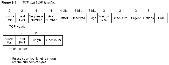
Figure 5-9 shows TCP and UDP header formats. Note the existence of both source and
destination port number fields in the TCP and UDP headers, but the absence of sequence
acknowledgment fields in the UDP header, as shown in Figure 5-9. UDP does not need these
fields because it makes no attempt to number the data for acknowledgments or resequencing.
Table 5-4
TCP and UDP Functional ComparisonFunction Description (TCP) Description (UDP)
Data transfer Continuous stream of ordered
data
Message (datagram) delivery
Multiplexing Receiving hosts decide the
correct application for which the
data is destined, based on port
number
Receiving hosts decide the
correct application for which the
data is destined, based on port
number
Reliable transfer Acknowledgment of data
using the sequence and
acknowledgment fields in the
TCP header
Not a feature of UDP
Flow control Process used to protect buffer
space and routing devices
Not a feature of UDP
Connections Process used to initialize port
numbers and other TCP header
fields
UDP is connectionless
226
Chapter 5: Network ProtocolsUDP gains some advantages over TCP by not using the sequence and acknowledgment fields.
The most obvious advantage of UDP over TCP is that there are fewer bytes of overhead. Not as
obvious is the fact that UDP does not require waiting on acknowledgments or holding the data
in memory until it is acknowledged. This means that UDP applications are not artificially
slowed by the acknowledgment process, and memory is freed more quickly.
Address Resolution Protocol
One common problem that CCNAs deal with on a regular basis is this: Given some Layer 3
address, what is its corresponding Layer 2 address? Address Resolution Protocol (ARP) is the
process by which this question is answered for an IP host on a LAN.
ARP is needed because to send an IP packet across some LAN, the data link header and trailer
(which encapsulate the packet) must first be created. The source MAC address in this new
header is known, but the destination MAC is not known in advance; ARP is the method IP uses
to discover the destination MAC address. Figure 5-10 shows an example of the ARP process.
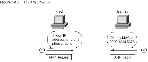
The ARP reply includes Barney’s MAC address in this example. An ARP cache holds the ARP
entries (IP address and MAC address in each entry) for each interface. If packets are flowing in
and out the interface from and to the IP address, the cache entry stays fresh. After a period of
disuse for an entry, the entry in the table is removed. Any need to send packets to that IP address
out that same interface after the ARP entry times out will require another ARP exchange.
From an architecture perspective, ARP is a Layer 3 function and is defined in RFC 826. From
a programming perspective, ARP calls the LAN data link layer code, which is indicative of a
Layer 3 protocol. Note the location of ARP in the architectural model in Figure 5-11.
TCP/IP Protocols
227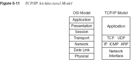
Internet Control Message Protocol
The CCNA exam requires that you know both the general concepts and several specifics about
the Internet Control Message Protocol (ICMP).
Control Message is the most descriptive part ofthe name—ICMP helps control and manage the work of IP and therefore is considered to be
part of TCP/IP’s network layer. RFC 792 defines ICMP and includes the following excerpt,
which describes the protocol well:
Occasionally a gateway or destination host will communicate with a source host, for
example, to report an error in datagram processing. For such purposes this protocol, the
Internet Control Message Protocol (ICMP), is used. ICMP uses the basic support of IP as
if it were a higher level protocol; however, ICMP is actually an integral part of IP, and
must be implemented by every IP module.
Several ICMP messages are in use in even the smallest IP network, so Cisco requires CCNAs
to be familiar with several of these messages. Table 5-5 lists several ICMP messages, with the
ones most likely to be on the exam noted with an asterisk. Not surprisingly, these are the same
messages used most often. The Destination Unreachable, Time Exceeded, and Redirect
messages will be described in more detail following Table 5-5.
Table 5-5
ICMP Message TypesMessage Purpose
*Destination Unreachable This tells the source host that there is a problem delivering a
packet.
*Time Exceeded The time it takes a packet to be delivered has become too long; the
packet has been discarded.
Source Quench The source is sending data faster than it can be forwarded; this
message requests that the sender slow down.
continues
228
Chapter 5: Network Protocols* More likely to be on the CCNA exam.
Each ICMP message contains a Type field and a Code field, as shown in Figure 5-12. The Type
field implies the message types from Table 5-5. The Code field implies a subtype; serial
subtypes will be shown in the following examples.
*Redirect The router sending this message has received some packet for
which another router would have had a better route; the message
tells the sender to use the better router.
*Echo This is used by the
ping command to verify connectivity.Parameter Problem This is used to identify a parameter that is incorrect.
Timestamp This is used to measure roundtrip time to particular hosts.
Address Mask Request/Reply This is used to inquire about and learn the correct subnet mask to
be used.
Router Advertisement and
Selection
This is used to allow hosts to dynamically learn the IP addresses
of the routers attached to the subnet.
Table 5-5
ICMP Message Types (Continued)Message Purpose

Destination Unreachable ICMP Message
The five separate
unreachable functions (codes) are accomplished using this single ICMPunreachable message. All five code types pertain directly to some IP, TCP, or UDP feature and
are better described by using Figure 5-13 as an example network.
Assume that Fred is trying to connect to the Web server, which uses TCP as the transport layer
protocol. Three of the ICMP unreachable codes would possibly be used by Routers A and B.
The other two codes would be used by the Web server. These ICMP codes would be sent to Fred
as a result of the packet originally sent by Fred.
A code meaning “Network Unreachable” would be used by Router A if Router A did not have
a route to 10.1.2.0/24. The message would be sent by Router A to Fred, in response to Fred’s
packet destined to 10.1.2.14.
TCP/IP Protocols
229
Host Unreachable is a code used if that single host is unavailable. If Router A had a route to
10.1.2.0/24, the packet would get to Router B. However, if the Web server is down, Router B
will not get an ARP reply from Web; Router B will send an unreachable back to Fred, with the
Host Unreachable code field.
Can’t Fragment is the third unreachable code that is likely to be sent by a router. If Router A or
Router B needed to fragment the packet, but the Do Not Fragment bit was set in the IP header,
the router would send an unreachable back to Fred with the Can’t Fragment value in the code
field.
If the packet successfully arrives at the Web server, two other unreachable codes are possible.
One implies that the protocol above IP, typically TCP or UDP, is not running on that host. This
is highly unlikely today. If true, this host would reply with an unreachable with the code field
value implying Protocol Unavailable. The final code field value is more likely today. If the
server was up but the Web server software was not running, the TCP/IP code on the server
would reply with an unreachable with the code field implying Port Unavailable. In other words,
the Web server software has not opened a listening socket connection using the Web server
well-known port of 80.
Cisco IOS documentation and configuration commands sometimes treat each different code
value as a separate message. For example, the documentation lists
ping responses, statingsomething like an “ICMP host unreachable” message. There is no such message, but there is a
“destination unreachable” with the Host Unreachable code set. The exam probably will not
expect you to know that there is no Host Unreachable message, though.
Table 5-6 summarizes the ICMP unreachable codes.
Table 5-6
ICMP Unreachable CodesUnreachable
Code When Used
Typically Sent
By…
Network
Unreachable
There is no match in a routing table for the destination of the
packet.
Router
Host Unreachable The packet can be routed to a router connected to the
destination subnet, but the host is not responding.
Router
continues
230
Chapter 5: Network ProtocolsTime Exceeded ICMP Message
The CCNA exam requires that you understand how routing protocols avoid creating routing
loops. However, if a loop occurs, the Time To Live (TTL) field in the IP header is used to time
out looping packets so that the packets do not loop forever.
The Time Exceeded ICMP message is used in conjunction with the IP TTL header field. One
of the two codes for Time Exceeded will be described here—namely, the Time To Live (TTL)
code option.
An analogy for Time Exceeded may help. In the 1970s, a science fiction movie called
Logan’sRun
was created. When they turned 30, citizens on this planet participated in a religiousceremony in which they were cremated; the reason was for population control. Logan turned 30
and decided that he did not like the rules—so he ran.
The TTL field in the IP header is like the counter used for citizens in
Logan’s Run. When thecounter expires, so does the packet. Each router decrements the TTL field in each packet header.
(The router does not actually calculate a time that should be decremented; it just decrements by
1.) However, if TTL decrements to 0, the packet is discarded. (For those who remember
Logan’sRun
, you can think of TTL as the Logan’s Run field.)The TTL exceeded option is used in a message generated by the router that discards the packet
when TTL expires. The router sends the “ICMP Time Exceeded, code Time To Live Exceeded”
message to the originator of the discarded packet. TTL is used to ensure that packets that are
looping do not do so forever. TTL exceeded lets the originating host know that a routing loop
may be occurring.
The
trace command uses the “TTL exceeded” message to its advantage. By purposefullysending IP packets (with a UDP transport layer) with TTL set to 1, an “ICMP Time Exceeded”
message is returned by the first router in the route. That’s because that router decrements TTL
to 0, causing it to discard the packet, and also sends the “TTL exceeded” message. The
tracecommand learns the IP address of the first router by receiving the “TTL exceeded” message
from that router. (The
trace command actually sends three successive packets with TTL=1.)Another set of three IP packets, this time with TTL=2, is sent by the
trace command. The firstCan’t Fragment The packet has the Don’t Fragment bit set, and a router must
fragment to forward the packet.
Router
Protocol
Unreachable
The packet is delivered to the destination host, but the
transport layer protocol is not available on that host.
Endpoint host
Port Unreachable The packet is delivered to the destination host, but the
destination port has not been opened by an application.
Endpoint host
Table 5-6
ICMP Unreachable Codes (Continued)Unreachable
Code When Used
Typically Sent
By…
TCP/IP Protocols
231router forwards these packets, but the second router discards it and sends a “TTL exceeded”
message as well. Eventually, a set of packets is delivered to the destination, which sends back
an “ICMP port unreachable” message. The original packets sent by the host
trace commanduse a destination port number that is very unlikely to be used so that the destination host will
return the “port unreachable” message. The “ICMP port unreachable” message signifies that the
packets reached the true destination host, without having TTL exceeded. Example 5-1 shows a
trace
command from a router (Router A) that is one hop away from a host; another router(Router B) has
debug ip icmp enabled, which shows the resulting TTL exceeded messages.The commands were performed in the network in Figure 5-13.
Redirect ICMP Message
ICMP redirect messages provide a very important element in routed IP networks. Many hosts
are preconfigured with a default router IP address. When sending packets destined to subnets
other than the one to which they are directly connected, these hosts send the packets to their
default router. If there is a better local router to which the host should send the packets, an ICMP
redirect can be used to tell the host to send the packets to this different router.
For example, in Figure 5-14, the PC uses Router B as its default router. However, Router A’s
route to subnet 10.1.4.0 is a better route. (Assume use of mask 255.255.255.0 in each subnet in
Figure 5-14.) The PC sends a packet to Router B (Step 1 in Figure 5-14). Router B then
forwards the packet based on its own routing table (Step 2); that route points through A, which
has a better route. Finally, Router B sends the ICMP redirect message to the PC (Step 3), telling
it to forward future packets destined for 10.1.4.0 to Router A instead. Ironically, the host can
ignore the redirect and keep sending the packets to Router B.
In summary, ICMP defines several message types and several subtypes, called codes. Popular
use of terminology treats each differing code as a different message; the exam is likely to treat
these codes as different messages as well, although it is unlikely that the level of granularity
will be important toward getting the right answer. Pay particular attention to the messages
denoted with asterisks in Table 5-5. Finally, RFC 792 is a short and straightforward RFC to read
if you want more information.
Example 5-1
ICMP debug on Router B, When Running trace Command on Router ARouterA#
trace 10.1.2.14Type escape sequence to abort.
Tracing the route to 10.1.2.14
1 10.1.3.253 8 msec 4 msec 4 msec
2 10.1.2.14 12 msec 8 msec 4 msec
RouterA#
___________________________________________________________________________
RouterB#
ICMP: time exceeded (time to live) sent to 10.1.3.251 (dest was 10.1.2.14)
ICMP: time exceeded (time to live) sent to 10.1.3.251 (dest was 10.1.2.14)
ICMP: time exceeded (time to live) sent to 10.1.3.251 (dest was 10.1.2.14)
232
Chapter 5: Network Protocols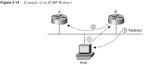
ICMP Echo Request and Echo Reply
The ICMP Echo and Echo Reply messages are sent and received by the
ping command. In fact,when people say that they sent a ping packet, they really mean that they sent an ICMP Echo
Request. These two messages are very much self-explanatory. The Echo Request simply means
that the host to which it is addressed should reply to the packet. The Echo Reply is the ICMP
message type that should be used in the reply. The Request includes some data, which can be
specified by the
ping command; whatever data is sent in the Echo Request is sent back in theEcho Reply.
The
ping command itself supplies many creative ways to use Echo Requests and Replies.For instance, the
ping command enables you to specify the length as well as the source anddestination address, and it also enables you to set other fields in the IP header. Example 5-6,
later in this chapter, shows a good example of the capabilities of the
ping command.FTP and TFTP
File Transfer Protocol (FTP) and Trivial File Transfer Protocol (TFTP) are two popularly used
file transfer protocols in a typical IP network. Most users use FTP, whereas router and switch
administrators use TFTP. Which is “better” depends partially on what is being done. A more
important question may typically be, “Which is supported on the devices that need to transfer
the file?” Given a choice today, most users will choose FTP because it has many more robust
features. TFTP is a favorite of router administrators, however, because the IOS does not support
FTP as an application.
TCP/IP Protocols
233FTP
FTP is a TCP-based application that has many options and features, including the capabilities
to change directories, list files using wildcard characters, transfer multiple files with a single
command, and use a variety of character sets or file formats. More important in this context is
the basic operation of FTP. Figures 5-15 and 5-16 show a typical FTP connection—or, better
stated, connections:

The connection shown in Figure 5-15 is called an
FTP control connection. When a user (FTPclient) asks to connect to an FTP server, a TCP connection is established to the FTP server’s
well-known port (21). The connection is established like any other TCP connection. The user
is typically required to enter a user name and password, which the server uses to authenticate
the files available to that user for read and write permissions. This security is based on the file
security on the server’s platform. Access to files on the client side is implied by the environment
from which the client created the FTP connection; again, this is dependent on the operating
system on the client platform. All the commands used to control the transfer of a file are sent
across this connection—hence the name FTP control connection.
At this point, the user has a variety of commands available to enable settings for transfer, change
directories, list files, and so forth. However whenever a
get or a put command is entered (ormget
or mput—m is for multiple) or the equivalent button is clicked, then a file is transferred.The data is transferred over a separate
TCP data connection. Figure 5-16 outlines the FTP dataconnection process.

As shown in Figure 5-16, another TCP connection is established, this time to well-known port
20. Using this convention, a file can be transferred without getting in the way of the control
connection. If many files are to be transferred rather than make a single control/data connection
for each file, the control connection is made once. The environment is defined using the control
connection, and these settings affect the functioning of the data connection. For instance, the
default directory to use in future transfers can be defined using commands on the control
234
Chapter 5: Network Protocolsconnection, as well as the type of data (binary or ASCII). The control connection stays up until
the user breaks it. While the control connection is up, a separate data connection is established
for each file transfer.
An additional step helps prevent hackers from breaking in and transferring files, as shown in
Figure 5-16. Rather than just creating a new connection, the client tells the server with an
application layer message what port number will be used for the new connection. The server
will not transfer the file (zzz, in this case) over any other data connection except the one to the
correct socket—the one with the client’s IP address, TCP, and the port number declared to the
server (1031, in this case).
TFTP
Trivial File Transfer Protocol (TFTP) is a UDP-based application with very basic features. One
of the reasons that such an application is needed (when the more robust FTP is available) is that
TFTP takes little memory to load and takes little time to program. With the advent of extremely
low-cost memory and processing, such advantages seem trivial. Practically speaking, if you
intend to transfer files frequently from your PC, FTP is probably what you will use. However,
to transfer files into and out of IOS-based routers and switches, Cisco supports TFTP, not FTP.
TFTP uses UDP, so there is no connection establishment and no error recovery by the transport
layer. However, TFTP uses application layer recovery by embedding a small header between
the UDP header and the data. This header includes codes—for instance, read, write, and
acknowledgment—along with a numbering scheme that numbers 512-byte blocks of data.
These block numbers are used to acknowledge receipt and resend the data. TFTP sends one
block and waits on an acknowledgment before sending another block—essentially, the
equivalent of a window size of 1.
Table 5-7 summarizes some features of TFTP and FTP.
Table 5-7
Comparison of FTP and TFTPFTP TFTP
Uses TCP Uses UDP
Uses robust control commands Uses simple control commands
Sends data over a separate TCP connection from
control commands
Uses no connections, due to UDP
Requires more memory and programming effort Requires less memory and programming effort
Is not supported as an application in IOS Is supported as an application in IOS
IP Addressing and Subnetting
235IP Addressing and Subnetting
Probably no one reading this would be shocked to hear that IP addressing is one of the most
important topics on the CCNA exam. A comfortable, confident understanding of IP addressing
and subnetting is required for success on any Cisco certification. For CCNA, questions directly
ask for your interpretation of an address, its network number, its subnet number, the other IP
addresses in the same subnet, the broadcast address, and the other subnets that could be used if
the same mask were in use. In other words, you had better know subnetting!
This section of the book provides two key functions. First, you will find an extensive review of
IP addressing and subnetting. Second, this section takes a structured look at how to answer
CCNA IP addressing questions. No other topic will be covered as extensively as IP addressing
and subnetting on the exam. This section helps you prepare for answering those questions
confidently and quickly.
IP Addressing Review
To pass the CCNA exam, you
must have complete familiarity with the terminology used withIP addressing. This terminology can sometimes get in the way of a good understanding of IP
addressing. Table 5-8 lists the IP terms used in the upcoming sections.
Table 5-8
IP Addressing TerminologyTerm Definition
IP address 32-bit number, usually written in dotted decimal form, that uniquely
identifies an interface of some computer.
Host address Another term for IP address.
Network The concept of a group of hosts.
Network number A 32-bit number, usually written in dotted decimal form, that represents
a network. This number cannot be assigned as an IP address to an
interface of some computer. The host portion of the network number has
a value of all binary 0s.
Network address Another name for network number.
Broadcast address A 32-bit number, usually written in dotted decimal form, that is used to
address all hosts in the network. The host portion of the broadcast
address has a value of all binary 1s. Broadcast addresses cannot be
assigned as an IP address.
Subnet The concept of a group of hosts, which is a subdivision of a network.
Subnet number A 32-bit number, usually written in dotted decimal form, that represents
all hosts in a subnet. This number cannot be used as an IP address for
some computer’s interface.
Subnet address Another term for subnet number.
continues
236
Chapter 5: Network ProtocolsClasses of Networks
Class A, B, and C networks provide three network sizes. By definition, all addresses in the same
network have the same numeric value network portion of the addresses. The rest of the address
is called the host portion of the address. Individual addresses in the same network all have a
different value in the host parts of the addresses but have identical values in the network part.
Class A networks have a 1-byte-long network part. That leaves 24 bits for the rest of the address,
or the host part. That means that 2
24 addresses are numerically possible in a Class A network.Similarly, Class B networks have a 2-byte-long network part, leaving 16 bits for the host portion
Subnetting The process of subdividing networks into smaller subnets. This is
jargon—for example, “Are you subnetting your network?”
Network mask A 32-bit number, usually written in dotted decimal form. The mask is
used by computers to calculate the network number of a given IP
address by performing a Boolean AND of the address and mask. The
mask also defines the number of host bits in an address.
Mask A generic term for a mask, whether it is a default mask or a subnet
mask.
Address mask Another term for a mask.
Default Class A mask The mask used for Class A networks when no subnetting is used. The
value is 255.0.0.0.
Default Class B mask The mask used for Class B networks when no subnetting is used. The
value is 255.255.0.0.
Default Class C mask The mask used for Class C networks when no subnetting is used. The
value is 255.255.255.0.
Subnet mask A non-default mask used when subnetting.
Network part or network
field
Term used to describe the first part of an IP address. The network part is
8, 16, or 24 bits for Class A, B, and C networks, respectively.
Host part or host field Term used to describe the last part of an IP address. The host part is 24,
16, or 8 bits for Class A, B, and C networks, respectively, when
subnetting is not used. When subnetting, the size of the host part
depends on the subnet mask chosen for that network.
Subnet part of subnet field Term used to describe the middle part of an IP address. The subnet part
is variable in size, based on how subnetting is implemented.
Table 5-8
IP Addressing Terminology (Continued)Term Definition
IP Addressing and Subnetting
237of the address. So, 2
16 possible addresses exist in a single Class B network. Finally, Class Cnetworks have a 3-byte-long network part, leaving only 8 bits for the host part, which implies
only 2
8 addresses in a Class C network. Table 5-9 summarizes the characteristics of Class A, B,and C networks.
* There are two reserved host addresses per network.
For example, Figure 5-17 shows a small network with addresses filled in. Network 8.0.0.0 is a
Class A network; Network 130.4.0.0 is a Class B network; Network 199.1.1.0 is a Class C
network.
Table 5-9
Sizes of Network and Host Parts of IP Addresses with No SubnettingAny Network of
This Class
Number of
Network Bytes
(Bits)
Number of Host
Bytes (Bits)
Number of Addresses per
Network*
A 1 (8) 3 (24) 2
24 minus two special casesB 2 (16) 2 (16) 2
16 minus two special casesC 3 (24) 1 (8) 2
8 minus two special cases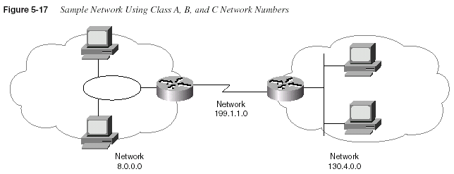
Network numbers look like addresses (in dotted decimal format), but they are not assignable to
any interface as an IP address. Conceptually, network numbers represent the group of all IP
addresses in the network. Numerically, the network number is built with a nonzero value in the
network part but with all 0s in the host part of the network number. Given the three examples
from Figure 5-17, Table 5-10 provides a closer look at the numerical version of the three
network numbers: 8.0.0.0, 199.1.1.0, and 130.4.0.0.
238
Chapter 5: Network ProtocolsMany different Class A, B, and C networks exist. If connecting to the Internet without using a
form of Address Translating Gateway (such as the Cisco PIX), then your firm must use
registered, unique network numbers. To that end, the Network Information Center (NIC)
assigns networks so that uniqueness is achieved. Table 5-11 summarizes the possible network
numbers, the total number of each type, and the number of hosts in each Class A, B, and C
network.
* Valid Network Numbers column shows actual network numbers. There are several reserved cases. For example,
network 0.0.0.0 (available for use as a broadcast address) and 127.0.0.0 (available for use as the loopback address)
are reserved. Networks 128.0.0.0, 191.255.0.0, 192.0.0.0, and 223.255.255.0 are also reserved.
Classifying a network as Class A, B, or C should become an instantaneous process before you
take the test. Memorize the ranges in the second column of Table 5-11. Also memorize the
number of octets in the network part of Class A, B, and C addresses, as shown in Table 5-9.
Masks and IP Address Formats
One common task that CCNAs run into is the interpretation of a network or subnet mask. This
mask is used for several purposes. One key purpose is to define the number of host bits in an
address. This mask also is used by computers when calculating the network or subnet number
of which that address is a member.
Table 5-10
Example Network Numbers, Decimal and BinaryNetwork Number Binary Representation, with Host Part Bold
8.0.0.0 0000 1000
0000 0000 0000 0000 0000 0000130.4.0.0 1000 0010 0000 0100
0000 0000 0000 0000199.1.1.0 1100 0111 0000 0001 0000 0001
0000 0000Table 5-11
List of All Possible Valid Network Numbers*Class
First Octet
Range
Valid Network
Numbers
Total Number
of This Class of
Network
Number of
Hosts per
Network
A 1 to 126 1.0.0.0 to
126.0.0.0
2
7 minus twospecial cases
2
24 minus twospecial cases
B 128 to 191 128.1.0.0 to
191.254.0.0
2
14 minus twospecial cases
2
16 minus twospecial cases
C 192 to 223 192.0.1.0 to
223.255.254.0
2
21 minus twospecial cases
2
8 minus twospecial cases
IP Addressing and Subnetting
239To fully appreciate what the mask is used for, you must understand the format of an IP address.
Consider Figure 5-18, which shows the format of Class A, B, and C addresses when no
subnetting is used.
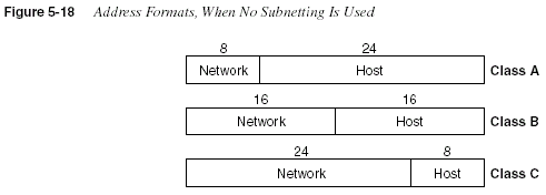
Notice that there are only two portions of the address—namely, the network part and the host
part. The only variable is whether the address in question is in a Class A, B, or C network.
The default mask used with each class of network defines the number of host bits. The mask
has binary 0 for each corresponding bit position in the address that is considered to be part of
the host portion of the address. Similarly, it appears that the mask implies the size and position
of the network part of the address; however, the network part is actually already implied by the
class of network. Table 5-12 summarizes the default masks and reflects the sizes of the two parts
of an IP address.
When subnetting, a third part of an IP address appears—namely, the subnet part of the address.
This field is created by “stealing” bits from the host part of the address. Figure 5-19 shows the
format of addresses when subnetting.
Three portions of the address now exist: network, subnet, and host. The network part size is
determined by the class (A, B, or C). The host part is determined by the subnet mask in use—
the number of bits of value 0 in the subnet mask define the number of host bits. The remaining
bits define the size of the subnet part of the address. For instance, a mask of 255.255.255.240,
used with a Class C network, implies four host bits. As shown in Figure 5-19, a Class C network
has 24 network bits. (The mask can be more easily converted to decimal using the table in
Appendix B.) The mask has four binary 0s at the end, implying 4 host bits.
Table 5-12
Class A, B, and C Networks—Network and Host Parts and Default MasksClass of Address
Size of Network
Part of Address, in
Bits
Size of Host Part of
Address, in Bits
Default Mask for
Each Class of
Network
A 8 24 255.0.0.0
B 16 16 255.255.0.0
C 24 8 255.255.255.0
240
Chapter 5: Network Protocols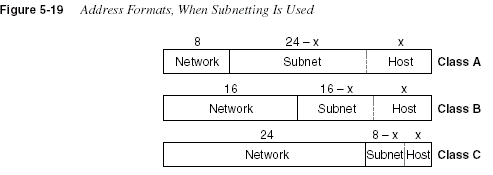
The number of hosts per network or subnet is defined by the number of host bits; 2
hostbits minustwo special reserved cases, is the number of assignable IP addresses in a network or subnet.
Similarly, the number of subnets of a network, assuming that the same mask is used on all
subnets, is defined by the number of subnet bits; 2
subnetbits is the number of usable IP subnetsof that network. Two special cases, the “zero subnet” and “broadcast subnet,” were reserved in
years past but are now usable.
Some definitions help summarize the concepts behind the address formats:
•
Two unique IP addresses in the same network have identical values in the network part oftheir address and have different values in their host parts.
•
Two unique IP addresses in the same subnet have identical values in the network part oftheir address, identical values in the subnet part of their address, and different values in
their host parts.
•
Two unique IP addresses in different subnets of the same Class A, B, or C network haveidentical values in the network part of their address and have different values in the subnet
part of their address.
•
Without subnetting, the network number, the network broadcast address, and allassignable IP addresses in the network have the same value in the network part of their
addresses.
•
With subnetting, the subnet number, the subnet broadcast address, and all assignable IPaddresses in the subnet have the same value in the network
and subnet parts of theiraddresses.
•
Most people treat the combined network and subnet parts of addresses as one part of theaddress and call it the subnet part of the address, or simply the
subnet.IP Grouping Concepts and Subnetting
Cisco requires that CCNAs exhibit a thorough understanding of IP subnetting. Almost every
organization with a network uses IP, and almost every one of these organizations uses
subnetting. Subnetting is simply the process of treating subdivisions of a single Class A, B, or
IP Addressing and Subnetting
241C network as if it were a network itself. By doing so, a single Class A, B, or C network can be
subdivided into many nonoverlapping subnets.
The needs for subnetting are both technical and administrative, as documented in the following
list:
•
All organizations connected to the Internet (and not using IP address translation) arerequired to use IP networks registered with the NIC.
•
IP protocols enforce the following grouping concept: All hosts in the same group must notbe separated by an IP router.
•
A corollary to the grouping concept is this: Hosts separated by an IP router must be inseparate groups.
•
Without subnetting, the smallest group is a single, entire Class A, B, or C network number.•
Without subnetting, the NIC would be woefully short of assignable networks.•
With subnetting, the NIC can assign one or a few network numbers to an organization, andthen the organization can subdivide those networks into subnets of more usable sizes.
An example drives these points home. Consider all network interfaces in Figure 5-20, and note
which ones are not separated by a router.
In Figure 5-20, six groupings exist, each of which is a Class B network. Four networks are more
obvious, those being the set of all interfaces attached to each of the four LANs. In other words,
the LANs attached to Routers A, B, C, and D are each a separate network. Additionally, the two
serial interfaces composing the point-to-point serial link between Routers C and D are both in
the same network because they are not separated by a router. Finally, the three router interfaces
composing the Frame Relay network with Routers A, B, and C would not be separated by an IP
router and would compose the sixth network.
If building this network today, the NIC would not assign six separate Class B network numbers,
as shown in Figure 5-20. Instead, you might get one or two Class C networks assigned by the
NIC, with the expectation that you would use subnetting.
Figure 5-21 illustrates a basic subnetting example. (
Basic is a term used for purposes in thisbook to denote subnetting examples for which the math is easy. More advanced subnetting is
covered later in this section.)
242
Chapter 5: Network Protocols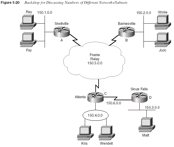
In the example in Figure 5-21, Class B network 150.150.0.0 is used (possibly assigned by the
NIC). The IP network designer has chosen a mask of 255.255.255.0, the last octet of which
implies 8 host bits. Because it is a Class B network, there are 16 network bits. Therefore, there
are 8 subnet bits, which happen to be bits 17 through 24—in other words, the third octet. Notice
that each subnet number in the figure shows a different value in the third octet, representing
each different subnet number.
Binary View of Subnetting
The benefit of a binary definition of subnetting is that it is exact. For a full understanding of
subnetting—particularly more advanced subnetting topics—as well as other IP addressing and
routing topics beyond the scope of this book, an exact definition is required. If your job will
include planning subnet number assignment or troubleshooting, this binary understanding will
be useful.
IP Addressing and Subnetting
243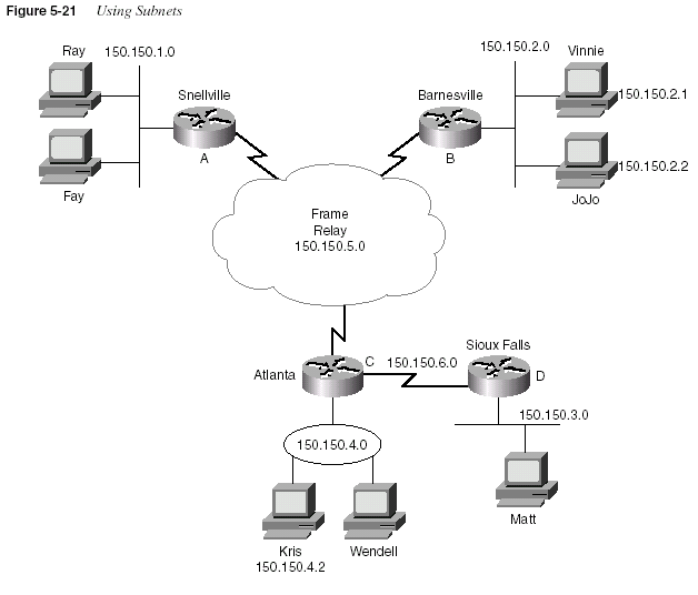
A review of some basic concepts relating to networks without subnetting can be used as a
comparison to networks with subnetting. When not subnetting, the default mask defines the
number of host bits. The mask accomplishes this by simply using binary 0 for each bit position
in the mask that corresponds to the host part of the address in question. For example, the mask
255.255.0.0 (Class B) has a value of all binary 0s in the last 16 bits. This implies 16 host bits at
the end of the address. The following list summarizes basic concepts when not using subnetting:
•
The mask defines the number of host bits in the host part of an address.•
Class A, B, and C rules define the number of network bits in the network part of theaddress.
•
Without subnetting, these two fields (network and host) compose the entire 32-bit address.•
Each host address in the network has the same value in the network part of the address.244
Chapter 5: Network Protocols•
Each host address in the network has a unique value in the host part of the address. (Forexample, 130.1.1.1 and 130.1.1.2 are in the same network but can be assigned to two
different network interfaces.)
Subnetting creates a third part of the address, called the
subnet field or subnet part. For example,using network 150.150.0.0 again, assume that you want a third field called the subnet field.
Several assertions are true in this case:
•
The Class A, B, and C network field sizes cannot be changed; they remain as 8, 16, and24 bits, respectively.
•
The IP address must still be 32 bits in length.•
Therefore, to create a third field called the subnet part of the address, some of the bitspreviously in the host part of the address are used
.The subnet part of an address identifies the different subdivisions of this network. An address
with a different value in the subnet field, as compared with a second address, is considered to
be in a different subnet. For example, examine the following three IP addresses that are part of
Table 5-13 and are valid addresses in Figure 5-21:
The example shows that the subnet field consists of bits 17 through 24 (the entire third byte).
150.150.2.1 and 150.150.2.2 are in the same subnet because they are in the same Class B
network and because
their subnet fields have the same value (0000 0010). 150.150.4.2 is in adifferent subnet of the same Class B network because the subnet field has a different value than
the first two addresses (0000 0100). 150.150.4.2 must be physically located with at least one IP
router between itself and 150.150.2.1 and 150.150.2.2.
Five Ways the Exam Will Test Your IP Addressing Knowledge
CCNAs deal with IP addressing concepts from many different perspectives every day. To pass
the CCNA exam, you’ll need to demonstrate the ability to think about IP addressing from each
of the following perspectives:
1
Given an IP address and mask, what is the network/subnet number?2
Given an IP address and mask, what is the network/subnet broadcast address?Table 5-13
Subnet Part of Sample AddressesAddress in Decimal Address in Binary
150.150.2.1 1001 0110 1001 0110
0000 0010 0000 0001150.150.2.2 1001 0110 1001 0110
0000 0010 0000 0010150.150.4.2 1001 0110 1001 0110
0000 0100 0000 0010IP Addressing and Subnetting
2453
Given an IP address and mask, what are the assignable IP addresses in that network/subnet?
4
Given a network number and a static subnet mask, what are the valid subnet numbers?5
Given a network number and a static subnet mask, how many hosts per subnet, and howmany subnets?
This section provides both a decimal and a binary algorithm for each perspective on IP
addressing. The decimal processes will help you find the answers more quickly; the binary
algorithms will help you more fully understand IP addressing.
Given an IP Address and Mask, What Is the Network/Subnet Number?
Both people and computers need to think about the question, “Which network is a particular
address a member of?” Humans care because it is useful in troubleshooting, planning, and
address assignment; computers need to know because the answer is a vital part of routing.
Decimal Algorithm for Deriving the Network Number, No Subnetting in Use
When no subnetting is in use, the decimal algorithm is as follows:
Step 1
Write down the IP address in decimal.Step 2
Copy below the IP address either the first one, two, or three dotteddecimal numbers of the address, based on whether the address is
a Class A, B, or C address, respectively.
Step 3
For the remaining dotted decimal numbers, record decimalvalue 0.
Table 5-14 shows some examples for deriving the network number (no subnetting in use) based
on the steps in the preceding list.
Table 5-14
Example Dissections of IP Addresses, No SubnettingIP Address (Step 1) Network Part (Step 2) Network Number (Step 3)
8.1.4.5 8 8.0.0.0
130.4.100.1 130.4 130.4.0.0
199.1.1.4 199.1.1 199.1.1.0
172.100.2.2 172.100 172.100.0.0
246
Chapter 5: Network ProtocolsBinary Algorithm for Deriving the Network Number, No Subnetting in Use
When a computer needs to answer this same question, it performs a Boolean math operation
called AND between the address in question and the mask. The result of the AND operation is
that the host bits are masked out—that is, changed to binary 0s. The binary process, with no
subnetting, is as follows:
Step 1
Write down the IP address in binary.Step 2
Write down the default mask appropriate for the class of address,in binary, beneath the binary IP address from Step 1.
Step 3
Record the results of the Boolean AND below the two numbers.Step 4
Convert the result of Step 3 back into decimal, 8 bits at a time.To perform the Boolean AND, each bit is examined in the address and is compared to the
corresponding bit in the mask. The AND operation results in a binary 1 if both the address and
the mask bits are also 1; otherwise, the result is 0. The Boolean AND for the addresses in Table
5-14 is shown in the following IP address table examples.
Consider the second example using address 130.4.100.1, mask 255.255.0.0. The binary mask
shows 16 binary 1s; any other binary value ANDed with binary 1 yields the original binary
value. In other words, any 16-bit number ANDed with 16 binary 1s yields the same number you
started with. So, the result shows 1000 0010 0000 0100 for the first 16 bits, which literally could
Address (Step 1) 8.1.4.5 0000 1000 0000 0001 0000 0100 0000 0101
Mask (Step 2) 255.0.0.0 1111 1111
0000 0000 0000 0000 0000 0000Result (Steps 3 and 4) 8.0.0.0 0000 1000 0000 0000 0000 0000 0000 0000
Address (Step 1) 130.4.100.1 1000 0010 0000 0100 0110 0100 0000 0001
Mask (Step 2) 255.255.0.0 1111 1111 1111 1111
0000 0000 0000 0000Result (Steps 3 and 4) 130.4.0.0 1000 0010 0000 0100 0000 0000 0000 0000
Address (Step 1) 199.1.1.4 1100 0111 0000 0001 0000 0001 0000 0100
Mask (Step 2) 255.255.255.0 1111 1111 1111 1111 1111 1111
0000 0000Result (Steps 3 and 4) 199.1.1.0 1100 0111 0000 0001 0000 0001 0000 0000
Address (Step 1) 172.100.2.2 1010 1100 0110 0100 0000 0010 0000 0010
Mask (Step 2) 255.255.0.0 1111 1111 1111 1111
0000 0000 0000 0000Result (Steps 3 and 4) 172.100.0.0 1010 1100 0110 0100 0000 0000 0000 0000
IP Addressing and Subnetting
247be copied from the binary version of the address. The last 16 bits of the mask are all binary 0s;
any value ANDed with a binary 0 yields a 0. So, no matter what value is in the last 16 bits of
the address, once ANDed with the mask, the result will be all binary 0s, as shown in the example
result. The result is called the
network number when no subnetting is used; the result is thesubnet number
when subnetting is used.Decimal Algorithm for Deriving the Subnet Number, Basic Subnetting
The decimal algorithm, when basic subnetting is in use, is as follows:
Step 1
Write down the IP address in decimal.Step 2
Copy below the IP address either the first one, two, or three dotteddecimal numbers of the address, based on whether the subnet
mask is 255.0.0.0, 255.255.0.0, or 255.255.255.0, respectively.
Step 3
For the remaining dotted decimal numbers, record decimalvalue 0.
This algorithm is very similar to the algorithm that is used when there is no subnetting. The only
difference is in Step 2. In fact, this later version of the algorithm would work fine when there is
no subnetting in use. Table 5-15 lists several examples.
* The third column of Table 5-15 can be thought of as Step 2 in the decimal algorithm.
** This example shows a Class C address, with default mask. No subnetting is in use in this case.
Binary Algorithm for Deriving the Subnet Number, Basic Subnetting
The binary algorithm to determine the subnet number, when using basic subnetting, is
practically identical to the algorithm used when there is no subnetting. Again, the key is in
knowing what subnet mask is in use. The binary process, with basic subnetting, is as follows:
Step 1
Write down the IP address in binary.Step 2
Write down the subnet mask used in this network, in binary,beneath the binary IP address from Step 1.
Table 5-15
Subnetting ExamplesIP Address Subnet Mask
Network and
Subnet Part* Full Subnet Number
8.1.4.5 255.255.0.0 8.1 8.1.0.0
130.4.100.1 255.255.255.0 130.4.100 130.4.100.0
199.1.1.4 255.255.255.0 199.1.1 199.1.1.0**
172.100.2.2 255.255.255.0 172.100.2 172.100.2.0
17.9.44.3 255.255.255.0 17.9.44 17.9.44.0
248
Chapter 5: Network ProtocolsStep 3
Record the results of the Boolean AND below the two numbers.Step 4
Convert the result of Step 3 back into decimal, 8 bits at a time.Repeating the same samples from Table 5-15, using the Boolean AND delivers the following
results:
An example network will be used as a backdrop to discuss this binary view of subnetting.
Figure 5-22 illustrates six different subnets. Table 5-16 provides the list of subnet numbers.
Address (Step 1) 8.1.4.5 0000 1000 0000 0001 0000 0100 0000 0101
Mask (Step 2) 255.255.0.0 1111 1111 1111 1111
0000 0000 0000 0000Result (Steps 3 and 4) 8.1.0.0 0000 1000 0000 0001 0000 0000 0000 0000
Address (Step 1) 130.4.100.1 1000 0010 0000 0100 0110 0100 0000 0001
Mask (Step 2) 255.255.255.0 1111 1111 1111 1111 1111 1111
0000 0000Result (Steps 3 and 4) 130.4.100.0 1000 0010 0000 0100 0110 0100 0000 0000
Address (Step 1) 199.1.1.4 1100 0111 0000 0001 0000 0001 0000 0100
Mask (Step 2) 255.255.255.0 1111 1111 1111 1111 1111 1111
0000 0000Result (Steps 3 and 4) 199.1.1.0 1100 0111 0000 0001 0000 0001 0000 0000
Address (Step 1) 172.100.2.2 1010 1100 0110 0100 0000 0010 0000 0010
Mask (Step 2) 255.255.255.0 1111 1111 1111 1111 1111 1111
0000 0000Result (Steps 3 and 4) 172.100.2.0 1010 1100 0110 0100 0000 0010 0000 0000
Address (Step 1) 17.9.44.3 0001 0001 0000 1001 0010 1100 0000 0011
Mask (Step 2) 255.255.255.0 1111 1111 1111 1111 1111 1111
0000 0000Result (Steps 3 and 4) 17.9.44.0 0001 0001 0000 1001 0010 1100 0000 0000
IP Addressing and Subnetting
249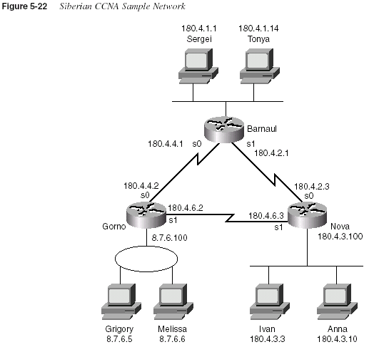
Table 5-16
Siberian SubnetsLocation of Subnet
Geographically Subnet Mask Subnet Number
Ethernet off router in Barnaul 255.255.255.0 180.4.1.0
Ethernet off router in Nova 255.255.255.0 180.4.3.0
Token Ring off router in Gorno 255.255.0.0 8.7.0.0
Serial link between Barnaul and
Nova
255.255.255.0 180.4.2.0
Serial link between Barnaul and
Gorno
255.255.255.0 180.4.4.0
Serial link between Nova and
Gorno
255.255.255.0 180.4.6.0
250
Chapter 5: Network ProtocolsKeep in mind that all the addresses on the same data link must be in the same subnet. For
example, Ivan and Anna must be in the same subnet, so performing either the easy decimal
algorithm or the more involved binary algorithm on either address will yield the same subnet
number, 180.4.3.0. If the answers are unclear, do several of these using the algorithm used by
computers. For example, using Ivan, the results will be as follows:
For additional practice, you may want to go to the scenarios section at the end of the chapter,
specifically to Scenarios 5-2 and 5-3.
Binary Algorithm for Deriving the Subnet Number, Difficult Subnetting
Difficult subnetting
is a term used in this book to denote subnetting when the mask is not all255s and 0s. The decimal algorithm for calculating the subnet, when basic subnetting is in use,
is more challenging. In fact, several math tricks come in handy so that the result can be
calculated without thinking about binary math. However, starting with the binary algorithm is
helpful.
These
difficult masks typically contain one of the values shown in Table 5-17. To speed up theprocess of examining these addresses (in case you are taking a timed test), memorizing the
decimal and binary numbers in Table 5-17 will be useful.
Address (Step 1) 180.4.3.3 1011 0100 0000 0100 0000 0011 0000 0011
Mask (Step 2) 255.255.255.0 1111 1111 1111 1111 1111 1111
0000 0000Result (Steps 3 and 4) 180.4.3.0 1011 0100 0000 0100 0000 0011 0000 0000
Table 5-17
Typical Difficult Mask ValuesDecimal Binary
0 0000 0000
128 1000 0000
192 1100 0000
224 1110 0000
240 1111 0000
248 1111 1000
252 1111 1100
254 1111 1110
255 1111 1111
IP Addressing and Subnetting
251The binary algorithm to determine the subnet number, when using difficult subnetting, is
identical to the algorithm used when there is no subnetting or basic subnetting. Again, the key
is in knowing what subnet mask is in use. The binary algorithm is as follows:
Step 1
Write down the IP address in binary.Step 2
Write down the subnet mask used in this network, in binary,beneath the binary IP address from Step 1.
Step 3
Record the results of the Boolean AND below the two numbers.Step 4
Convert the result of Step 3 back into decimal, 8 bits at a time.The biggest obstacle to understanding this algorithm is failing to realize this one fact: Binarydecimal-
binary conversion is independent of the size of the network, subnet, and host fields.
Conversion always is from one decimal number to eight binary digits, and vice versa.
Typically, an example usually helps. Consider the following binary example:
Ignoring the decimal numbers on the left, a slow examination of the binary address, mask, and
Boolean AND result shows that the conversion to binary and AND are correct as shown. The
typical difficulty is the step of conversion. Many people want to convert the 12-bit host field to
a decimal number and the 4-bit subnet field to a decimal number. Instead, for the last step
(conversion to decimal), convert the first 8-bit set to decimal (0000 1000 converted to decimal
8). Likewise, convert the second 8-bit set (the second byte) to decimal (0000 0001 converted to
decimal 1). Then convert the entire third byte to decimal (0110 0000 converted to decimal 96).
Finally, convert the entire last byte to decimal (0000 0000 converted to decimal 0). The third
byte contains the entire subnet field and part of the host field; the binary-to-decimal conversion
ignores the subnet/host boundaries, always using byte boundaries.
The following examples are shown as additional examples of deriving the subnet number when
a more difficult mask is used:
Address 8.1.100.5 0000 1000 0000 0001 0110 0100 0000 0101
Mask 255.255.240.0 1111 1111 1111 1111 1111 0000 0000 0000
Result 8.1.96.0 0000 1000 0000 0001 0110 0000 0000 0000
Address (Step 1) 130.4.100.129 1000 0010 0000 0100 0110 0100 1000 0001
Mask (Step 2) 255.255.255.128 1111 1111 1111 1111 1111 1111 1000 0000
Result (Steps 3 and 4) 130.4.100.128 1000 0010 0000 0100 0110 0100 1000 0000
Address (Step 1) 199.1.1.4 1100 0111 0000 0001 0000 0001 0000 0100
Mask (Step 2) 255.255.255.224 1111 1111 1111 1111 1111 1111 1110 0000
Result (Steps 3 and 4) 199.1.1.0 1100 0111 0000 0001 0000 0001 0000 0000
252
Chapter 5: Network ProtocolsDecimal Algorithm for Deriving the Subnet Number, Difficult Subnetting
The decimal algorithm that I like best for difficult subnetting works well. However, this
algorithm is not very helpful for understanding subnetting. So, if you understand subnetting and
are willing to use the more time-consuming binary algorithm on the exam for the difficult cases,
you may want to skip this section to avoid getting confused. The algorithm is as follows:
Step 1
Write down the IP address in decimal.Step 2
Write down the mask in decimal.Step 3
Examine the mask. One of the four octets will have a value besides255 or 0; otherwise, this would not be considered to be a difficult
case. The octet with the non-255, non-0 value is considered to be
the “interesting” octet. The other three are considered “boring.”
Write down the number (1, 2, 3, or 4) of the interesting octet. (For
example, mask 255.255.240.0 has an interesting third octet.)
Step 4
Subtract the mask’s interesting octet value from 256. Call thatvalue the
multiplier. Write it down.Step 5
For any boring octets to the left of the interesting octet, copy thoseoctets’ values onto your paper, leaving space for the remaining
octets. This will be where you record your subnet number.
Step 6
For any boring octets to the right of the interesting octet, record avalue 0 in your subnet number. One of the four octets should still
be empty—the interesting octet.
Step 7
Examine the interesting octet of the original IP address. Discoverthe multiple of the
multiplier closest to this number, but less thanthe number. Write down this interesting multiple of the multiplier
into the interesting octet of the subnet number.
For those of you in doubt, examine the examples that follow. In each case, the steps in the
algorithm are shown. The crux of the algorithm is to search for the integer multiple of the
multiplier
that is close to, but less than, the value in the interesting octet of the IP address.Address (Step 1) 172.100.201.2 1010 1100 0110 0100 1100 1001 0000 0010
Mask (Step 2) 255.255.254.0 1111 1111 1111 1111 1111 1110 0000 0000
Result (Steps 3 and 4) 172.100.200.0 1010 1100 0110 0100 1100 1000 0000 0000
Address (Step 1) 17.9.44.70 0001 0001 0000 1001 0010 1100 0100 0110
Mask (Step 2) 255.255.255.192 1111 1111 1111 1111 1111 1111 1100 0000
Result (Steps 3 and 4) 17.9.44.64 0001 0001 0000 1001 0010 1100 0100 0000
IP Addressing and Subnetting
253Address (Step 1) 130.4.101.129
Mask (Step 2) 255.255.252.0
Interesting octet (Step 3) 3
Multiplier (Step 4) 256 – 252 = 4
Subnet (boring octets to the left) (Step 5) 130.4.____._____
Subnet (boring octets to the right) (Step 6) 130.4._____.0
Subnet (Step 7) 130.4.100.0
Address (Step 1) 199.1.1.4
Mask (Step 2) 255.255.255.224
Interesting octet (Step 3) 4
Multiplier (Step 4) 256 – 224 = 32
Subnet (boring octets to the left) (Step 5) 199.1.1.____
Subnet (boring octets to the right) (Step 6) 199.1.1._____
Subnet (Step 7) 199.1.1.0
Address (Step 1) 172.100.201.2
Mask (Step 2) 255.255.254.0
Interesting octet (Step 3) 3
Multiplier (Step 4) 256 – 254 = 2
Subnet (boring octets to the left) (Step 5) 172.100.____.____
Subnet (boring octets to the right) (Step 6) 172.100.____.0
Subnet (Step 7) 172.100.200.0
Address (Step 1) 17.9.44.70
Mask (Step 2) 255.255.255.192
Interesting octet (Step 3) 4
Multiplier (Step 4) 256 – 192 = 64
Subnet (boring octets to the left) (Step 5) 17.9.44.____
Subnet (boring octets to the right) (Step 6) 17.9.44.____
Subnet (Step 7) 17.9.44.64
254
Chapter 5: Network ProtocolsGiven an IP Address and Mask, What Is the Network/Subnet Broadcast Address?
CCNAs are expected to be able to derive the valid, assignable addresses in any subnet;
calculation of the broadcast address of the subnet is a vital part of the process. As mentioned
earlier, there are two reserved numbers in each network or subnet. One number is the network
number or subnet number, which is used to represent the entire network or subnet. The other
reserved number is called the
broadcast address. This number is used to represent all IPaddresses in the network or subnet. The broadcast address is used when a packet must be sent
to all hosts in a network or subnet. All hosts receiving the packet should notice that the packet
is destined for their own network or subnet broadcast address and then process the packet.
The broadcast address for a network is particularly important when planning an IP addressing
structure for a network. Take a look at the following definition:
The network/subnet number is the lowest value numerically in that network/subnet. The
broadcast address is the
largest value numerically in that network/subnet. The valid,assignable addresses in that network are the numbers between the network/subnet number
and the broadcast address.
Decimal Algorithm for Deriving the Broadcast Address, No Subnetting or Basic
Subnetting
The algorithms, both binary and decimal, for deriving the broadcast addresses are similar to the
same algorithms for deriving the subnet numbers. The algorithms used for basic subnetting are
used as a basis for the following algorithms for deriving the broadcast addresses. First, the
decimal algorithm is as follows:
Step 1
Write down the IP address in decimal.Step 2
Copy below the IP address either the first one, two, or three dotteddecimal numbers of the address, based on whether the subnet
mask is 255.0.0.0, 255.255.0.0, or 255.255.255.0, respectively.
Step 3
For the remaining dotted decimal numbers, record decimal value255.
The only difference between this algorithm and the one to derive the subnet number is that Step
3 directs you to plug in 255 instead of 0. Some examples follow in Table 5-18.
Table 5-18
Subnetting ExamplesIP Address (Step 1) Subnet Mask
Network and
Subnet Part (Step 2)
Broadcast Address
(Step 3)
8.1.4.5 255.255.0.0 8.1 8.1.255.255
130.4.100.1 255.255.255.0 130.4.100 130.4.100.255
199.1.1.4 255.255.255.0 199.1.1 199.1.1.255*
IP Addressing and Subnetting
255* This example shows a Class C address, with default mask. The broadcast address in that case is a network
broadcast, not a subnet broadcast address.
Binary Algorithm for Deriving the Broadcast Address
The binary algorithm to determine the broadcast address when using no subnetting or basic
subnetting is a little trickier than the similar algorithm for finding the subnet number. The
algorithm shown here is not really what computers use, but it is more instructive about how
broadcast addresses are structured. It starts by repeating the binary algorithm for computing the
subnet number and then adding two short steps. The algorithm is as follows:
Step 1
Write down the IP address in binary.Step 2
Write down the subnet mask used in this network, in binary,beneath the binary IP address from Step 1.
Step 3
Record the results of the Boolean AND below the two numbers.(This is the subnet number.)
Step 4
Copy down the network and subnet bits of the subnet number ontothe next line. This is the beginning of the broadcast address.
Step 5
Fill in the host bit values with all binary 1s. This is the broadcastaddress.
Step 6
Convert the result of Step 5 back into decimal, 8 bits at a time.As usual, a few examples will help:
172.100.2.2 255.255.255.0 172.100.2 172.100.2.255
17.9.44.3 255.255.255.0 17.9.44 17.9.44.255
Address (Step 1) 8.1.4.5 0000 1000 0000 0001 0000 0100 0000 0101
Mask (Step 2) 255.255.0.0 1111 1111 1111 1111
0000 0000 0000 0000Boolean AND (Step 3) 8.1.0.0 0000 1000 0000 0001 0000 0000 0000 0000
Broadcast address (Steps 4 to 6) 8.1.255.255 0000 1000 0000 0001
1111 1111 1111 1111Address (Step 1) 130.4.100.1 1000 0010 0000 0100 0110 0100 0000 0001
Mask (Step 2) 255.255.255.0 1111 1111 1111 1111 1111 1111
0000 0000Boolean AND (Step 3) 130.4.100.0 1000 0010 0000 0100 0110 0100 0000 0000
Broadcast address (Steps 4 to 6) 130.4.100.255 1000 0010 0000 0100 0110 0100
1111 1111Table 5-18
Subnetting Examples (Continued)IP Address (Step 1) Subnet Mask
Network and
Subnet Part (Step 2)
Broadcast Address
(Step 3)
256
Chapter 5: Network ProtocolsDecimal Algorithm for Deriving the Broadcast Address, Difficult Subnetting
The decimal algorithm for deriving the broadcast address when difficult subnetting is used is
shown next. When in doubt, use the binary algorithm. However, the following decimal
algorithm will yield the correct results:
Step 1
Write down the IP address in decimal.Step 2
Write down the mask in decimal.Step 3
Examine the mask. One of the four octets will have a value besides255 or 0; otherwise, this would not be considered to be a
“difficult” case. The octet with the non-255, non-0 value is
considered to be the “interesting” octet. The other three are
considered “boring.” Write down the number (1, 2, 3, or 4) of the
interesting octet. (For example, mask 255.255.240.0 has an
interesting third octet.)
Step 4
Subtract the mask’s interesting octet’s value from 256. Call thatvalue the
multiplier. Write it down.Step 5
For any boring octets to the left of the interesting octet, copy thoseoctets from the subnet onto a new line on your paper, leaving
space for the remaining octets. This line will be where you record
the broadcast address.
Address (Step 1) 199.1.1.4 1100 0111 0000 0001 0000 0001 0000 0100
Mask (Step 2) 255.255.255.0 1111 1111 1111 1111 1111 1111
0000 0000Boolean AND (Step 3) 199.1.1.0 1100 0111 0000 0001 0000 0001 0000 0000
Broadcast address (Steps 4 to 6) 199.1.1.255 1100 0111 0000 0001 0000 0001
1111 1111Address (Step 1) 172.100.2.2 1010 1100 0110 0100 0000 0010 0000 0010
Mask (Step 2) 255.255.255.0 1111 1111 1111 1111 1111 1111
0000 0000Boolean AND (Step 3) 172.100.2.0 1010 1100 0110 0100 0000 0010 0000 0000
Broadcast address (Steps 4 to 6) 172.100.2.255 1010 1100 0110 0100 0000 0010
1111 1111Address (Step 1) 17.9.44.3 0001 0001 0000 1001 0010 1100 0000 0011
Mask (Step 2) 255.255.255.0 1111 1111 1111 1111 1111 1111
0000 0000Boolean AND (Step 3) 17.9.44.0 0001 0001 0000 1001 0010 1100 0000 0000
Broadcast address (Steps 4 to 6) 17.9.44.255 0001 0001 0000 1001 0010 1100
1111 1111IP Addressing and Subnetting
257Step 6
For any boring octets to the right of the interesting octet, record avalue of 255 in the broadcast address (the same number as in Step
5.) One of the four octets should still be empty—the interesting
octet.
Step 7
Examine the interesting octet of the original IP address. Discoverthe multiple of the
multiplier closest to this number but greaterthan the number. Subtract 1 from this multiple. Write down this
value (1 less than the integer multiple of the multiplier) in the
interesting octet of the broadcast address.
For those of you in doubt, examine the examples that follow. In each case, the steps in the
algorithm are shown. The crux of the algorithm is to search for the integer multiple of the
multiplier
that is close to but greater than the value in the interesting octet of the IP address.2 130.4.101.129
Mask (Step 2) 255.255.252.0
Interesting octet (Step 3) 3
Multiplier (Step 4) 256 – 252 = 4
Broadcast address (boring octets to the left) (Step 5) 130.4.____._____
Broadcast address (boring octets to the right) (Step 6) 130.4._____.255
Broadcast address (104 is the closest multiple of 4 and is greater than 101;
104 – 1 = 103) (Step 7)
257
Address (Step 1) 199.1.1.5
Mask (Step 2) 255.255.255.224
Interesting octet (Step 3) 4
Multiplier (Step 4) 256 – 224 = 32
Broadcast address (boring octets to the left) (Step 5) 199.1.1.____
Broadcast address (boring octets to the right) (Step 6) 199.1.1._____
Broadcast address (32 is the closest multiple of 32 and is greater than 4;
32 – 1 = 31) (Step 7)
199.1.1.31
Address (Step 1) 172.100.201.2
Mask (Step 2) 255.255.254.0
Interesting octet (Step 3) 3
Multiplier (Step 4) 256 – 254 = 2
258
Chapter 5: Network ProtocolsGiven an IP Address and Mask, What Are the Assignable IP Addresses in That Network/
Subnet?
CCNAs deal with the question, “What IP addresses are in this subnet?” on a regular basis. This
section describes how to answer this question if you know how to derive the subnet and
broadcast addresses. Simply put, the valid IP addresses that are available for assignment in a
subnet are those numerically between the subnet number and the broadcast address.
There is little else to be considered. Certainly, no decimal or binary algorithm needs to be
considered for such a simple concept, right? Table 5-19 shows some familiar IP addresses and
the corresponding IP addresses in the same subnet.
The ranges seem obvious. However, look at the 172.100.200.0 subnet. How many assignable
IP addresses are in that subnet, and what are those addresses? Is 172.100.200.255 valid? What
about 172.100.201.0? In fact, both are valid IP addresses when using 255.255.254.0 as the
Broadcast address (boring octets to the left) (Step 5) 172.100.____.____
Broadcast address (boring octets to the right) (Step 6) 172.100.____.255
Broadcast address (202 is the closest multiple of 2 and is greater than 201;
202 – 1 = 201) (Step 7)
172.100.201.255
Address (Step 1) 17.9.44.70
Mask (Step 2) 255.255.255.192
Interesting octet (Step 3) 4
Multiplier (Step 4) 256 – 192 = 64
Broadcast address (boring octets to the left) (Step 5) 17.9.44.____
Broadcast address (boring octets to the right) (Step 6) 17.9.44.____
Broadcast address (128 is the closest multiple of 64 and is greater than 70;
128 – 1 = 127) (Step 7)
17.9.44.127
Table 5-19
Assignable AddressesSubnet Number Subnet Mask
Broadcast
Address
Range of Assignable
Addresses
130.4.100.0 255.255.252.0 130.4.103.255 130.4.100.1 to 130.4.103.254
199.1.1.0 255.255.255.224 199.1.1.31 199.1.1.1 to 199.1.1.30
172.100.200.0 255.255.254.0 172.100.201.255 172.100.200.1 to
172.100.201.254
17.9.44.64 255.255.255.192 17.9.44.127 17.9.44.65 to 17.9.44.126
IP Addressing and Subnetting
259mask. The rule is that the subnet numbers (and also the broadcast addresses) are not usable as
an IP address. Otherwise, the addresses are assignable to an interface.
Given a Network Number and a Static Subnet Mask, What Are the Valid Subnet Numbers?
One of the reasons you find so many different slants on IP addressing in this chapter is that the
CCNA exam questions you about IP in many different ways. The question in the heading of this
section is unlikely to be the exact question, however. You should expect to see something like,
“Which of the following are valid subnets of network X, using mask Y?,” followed by the
suggested answers. If you can figure out all the subnets of that network, you should be able to
answer the multiple-choice exam question easily.
A few additional facts will help you in thinking about the possible subnet numbers:
•
All subnet numbers have all binary 0s in the host part of the subnet number.•
All subnet numbers of the same Class A, B, or C network have identical values in thenetwork part of the subnet numbers.
•
All subnet numbers of the same Class A, B, or C network have different values in thesubnet part of the subnet numbers.
In other words, the only thing that is different about two different subnets of the same network
is the subnet part of the subnet number. The network and host parts are identical. An example
helps in this case. Examine Figure 5-23, which shows a familiar network with six subnets.
Figure 5-23 shows six subnets of network 150.150.0.0. Subnet mask 255.255.255.0 is used,
implying two network octets, one subnet octet, and one host octet. The subnets already used in
this example are as follows:
•
150.150.1.0•
150.150.2.0•
150.150.3.0•
150.150.4.0•
150.150.5.0•
150.150.6.0As long as you can find another value not already used in the third byte, you can find another
subnet number. In fact, simply counting sequentially, subnet numbers continue—150.150.7.0,
150.150.8.0, and so on, up through 150.150.254.0. That gives a total of 254 subnets, assuming
that the zero and broadcast subnets are not used.
260
Chapter 5: Network Protocols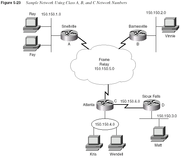
Decimal Algorithm for Deriving the Valid Subnets with Basic Subnetting
Time counts when taking the CCNA exam, so it’s a good idea to take advantage of the easier
decimal algorithms to derive facts about subnetting. The algorithm for deriving the subnet
numbers of a network, given a static, basic mask, is extremely intuitive. Two cases for the
decimal algorithm will be examined here: a Class A network subnetted using mask 255.255.0.0,
and a Class B network subnetted using mask 255.255.255.0:
Step 1
Write down the 1 or 2 bytes of the network number.Step 2
Leave a space immediately to the right to add a value in the nextoctet.
IP Addressing and Subnetting
261Step 3
Write down two octets (in the case of Class A) or one octet (in thecase of Class B) of 0 after the one-octet space left in Step 2,
leaving a number with three octets written and an open space in
the subnet part of the number.
Step 4
Write down a 1 in the open octet.Step 5
Repeat Steps 1 through 4, but in Step 4 add 1 to the number.Continue repeating these steps until you reach 254.
A similar algorithm is used when a Class A network is subnetted, using mask 255.255.255.0,
although that is not shown here.
The number of valid subnets is an important concept when deriving the actual subnet numbers.
How many should you expect to find? The formula is very straightforward, with a few twists on
the real answer. First, the formula:
2
number-of-subnet-bitsThe previous example in Figure 5-23 provides a good context in which to consider the
formula. A Class B network 150.150.0.0 is used, so there are 16 network bits. The mask is
255.255.255.0, so there are 8 host bits. That leaves 8 subnet bits—2
8 = 256, for 256 subnets.From the previous example, 150.150.0.0 is the first subnet, and 150.150.255.0 was the last,
which is consistent with the formula.
Two previously reserved cases, 150.150.0.0 and 150.150.255.0, were not used in the example.
The first of these, which is called the
zero subnet because the subnet value is all binary 0s, isusable only if the
ip subnet-zero global command is configured. The other subnet, called thebroadcast subnet
because it looks like a typical broadcast address, is usable without any specialconfiguration.
NOTE
Do not confuse the zero subnet and broadcast subnet with the two reserved IP addresses in eachsubnet. There are still two reserved addresses in each subnet that cannot be assigned to any
interface as an IP address. Those two numbers are the numbers used for the subnet number itself
and the broadcast address for the subnet.
Binary Algorithm for Deriving the Valid Subnets with Basic and Difficult
Subnetting
This section details a binary algorithm you can use to derive the subnet numbers. With basic
subnetting, you probably would not want to go through this much trouble. However, with
262
Chapter 5: Network Protocolsdifficult subnetting, the binary algorithm will be useful, at least until you become comfortable
with the decimal algorithm. The following binary algorithm is valid for basic subnetting as well.
Step 1
Reserve space to record a series of 32-bit numbers, one over theother. Also leave space between each nibble and byte on each line
for better readability.
Step 2
Write down the 8, 16, or 24 bits of the network part of the address,in binary, on each line.
Step 3
Write down binary 0s in the host field on each line. This shouldresult in a long list of binary numbers, with the subnet bits
unrecorded at this point.
Step 4
Write down all binary 0s in the subnet bit positions of the firstnumber in the list. This is the first subnet number, in binary. This
is also the
zero subnet.Step 5
Add binary 1 to the subnet field in the previous line, and record theresult in the subnet field of the next line.
Step 6
Repeat Step 5 until the subnet field is all binary 1s. That is the lastsubnet number, which is also the broadcast subnet.
Step 7
Convert any of these 32-bit numbers back to decimal, 8 bits at atime. IGNORE THE BOUNDARIES BETWEEN THE SUBNET
AND HOST FIELDS—do the conversion 8 bits at a time.
As usual, an example is better than a generic algorithm. First, a repeat of the 150.150.0.0,
255.255.255.0 example will be shown. Then network 150.150.0.0, with a different mask
of 255.255.248.0, will be shown. Table 5-20 shows the first several iterations of 150.150.0.0,
mask 255.255.255.0, but with a few of the intermediate subnet numbers not shown.
Table 5-20
Valid Subnet NumbersStep 2 (only one line shown) 1001 0110 1001 0110
Step 3 (only one line shown) 1001 0110 1001 0110 0000 0000
Step 4 1001 0110 1001 0110
0000 0000 0000 0000 150.150.0.0Step 5 1001 0110 1001 0110
0000 0001 0000 0000 150.150.1.0Step 6 1001 0110 1001 0110
0000 0010 0000 0000 150.150.2.0Step 6 1001 0110 1001 0110
0000 0011 0000 0000 150.150.3.0Step 6 1001 0110 1001 0110
0000 0100 0000 0000 150.150.4.0Step 6 1001 0110 1001 0110
0000 0101 0000 0000 150.150.5.0Skipped a few for brevity
Step 6 1001 0110 1001 0110
1111 1111 0000 0000 150.150.255.0IP Addressing and Subnetting
263As Table 5-20 shows, the same 256 subnet numbers are derived with the binary algorithm as
with the decimal algorithm. The second example shows one not-so-obvious (at least in decimal)
case with difficult subnetting (Table 5-21).
So, with 5 subnet bits, there should be 2
5 or 32 subnets, including the zero and broadcastsubnets. Examining the third octet of the decimal subnet numbers, with a little imagination, the
32 subnet numbers are 150.150.
x.0, where x is an integer multiple of 8. The zero subnet is150.150.0.0, and 150.150.248.0 is the broadcast subnet.
Decimal Algorithm for Deriving the Valid Subnets with Basic and Difficult
Subnetting
CCNAs will need to derive the valid subnets of a network on a regular basis, so a decimal
algorithm to derive the valid subnets—even when difficult subnetting is used—proves
invaluable. With some practice, you can use the following algorithm without pen and paper or
a calculator. This algorithm works only if the subnet field is less than 8 bits. If the subnet field
is larger, you can use a similar algorithm (which is not shown) once you understand this specific
algorithm. The algorithm is as follows:
Step 1
Based on the network number and mask, all subnet bits are in 1byte. (Having all subnet bits in 1 byte is an assumption used for
this algorithm.) This is the “interesting” byte. Write down which
byte is the interesting byte. The other 3 octets/bytes are considered
“boring.”
Step 2
Find the number of host bits in the interesting octet, and call thatnumber N. 2
N is called the increment. Record that number.Table 5-21
Valid Subnet Numbers, 150.150.0.0, Mask 255.255.248.0Step 2 (only one line shown) 1001 0110 1001 0110
Step 3 (only one line shown) 1001 0110 1001 0110 000 0000 0000
Step 4 1001 0110 1001 0110
0000 0000 0000 0000 150.150.0.0Step 5 1001 0110 1001 0110
0000 1000 0000 0000 150.150.8.0Step 6 1001 0110 1001 0110
0001 0000 0000 0000 150.150.16.0Step 6 1001 0110 1001 0110
0001 1000 0000 0000 150.150.24.0Step 6 1001 0110 1001 0110
0010 0000 0000 0000 150.150.32.0Step 6 1001 0110 1001 0110
0010 1000 0000 0000 150.150.40.0Skipped a few for brevity
Step 6 1001 0110 1001 0110
1111 1111 0000 0000 150.150.248.0264
Chapter 5: Network ProtocolsStep 3
Create a list, one entry above the other, that contains repeatedcopies of the decimal network number. However, leave the
interesting octet blank. This will become the list of subnet
numbers.
Step 4
In the first number in the list, in the interesting octet, write adecimal 0. This is the first (zero) subnet.
Step 5
For each successive entry in your list of subnets, add the incrementto the previous entry’s interesting octet value, and record that
value in the interesting octet.
Step 6
When 256 is the value to be recorded in Step 5, you havecompleted the list of subnet numbers.
Two examples of the nonbinary algorithm will be shown. First, Table 5-22 shows the familiar
150.150.0.0, mask 255.255.248.0
Table 5-22
Valid Subnet Numbers, 150.150.0.0, Mask 255.255.248.0Step 1 Interesting byte is 3
Step 2 Increment 2
3 = 8Step 3 150.150.____.0
150.150.____.0
150.150.____.0
150.150.____.0
150.150.____.0 and so forth
Step 4 150.150.
0.0Step 5 150.150.
8.0150.150.
16.0150.150.
24.0Skipped a few for brevity
150.150.
248.0 (This is the last one)Step 6 150.150.256.0 (This one is invalid)
IP Addressing and Subnetting
265For one other example, Table 5-23 shows network 128.1.0.0, with mask 255.255.252.0.
Given a Network Number and a Static Subnet Mask, How Many Hosts per Subnet, and
How Many Subnets?
Finally, one more way the exam is likely to test your knowledge of IP addressing and subnetting
is to ask which subnet masks will meet a set of requirements. This last type of question would
be phrased as something like, “If you need at least 30 hosts in each subnet and only 4 subnets,
and if you are using network 192.1.1.0, which of the following masks meet your requirements?”
To answer these types of questions confidently, you must have a good understanding of the three
parts of an IP address. Figure 5-19 earlier in the chapter shows the network, subnet, and host
parts of an address. These fields and their sizes are important because they identify the number
of subnets possible and the number of hosts per subnet.
The number of hosts per subnet is defined by this formula:
2
number of host bits – 2The number of host bits in an address is equal to the number of binary 0s in the subnet mask.
Table 5-23
Valid Subnet Numbers, 128.1.0.0, Mask 255.255.252.0Step 1 Interesting byte is 3
Step 2 Increment 2
2 = 4Step 3 128.1.____.0
128.1.____.0
128.1.____.0
128.1.____.0
128.1.____.0 and so forth
Step 4 128.1.
0.0Step 5 128.1.
4.0128.1.
8.0128.1.
12.0Skipped a few for brevity
128.1.
252.0 (This is the last one)Step 6 128.1.256.0 (This one is invalid)
266
Chapter 5: Network ProtocolsThe number of subnets per network is defined by this formula:
2
number of subnet bitsThe number of subnet bits is based on the mask and class of address. The number of subnet bits
is:
32 – (number of network bits) – (number of host bits)
NOTE
In some documents, the number of subnets is shown as 2 less than 2number of subnet bits, implyingtwo reserved cases. These two cases are no longer reserved, however, and can be used.
An algorithm may help, along with some samples.
Step 1
Write down the network number and mask in question.Step 2
Write down the number of network bits based on Class A, B, andC rules.
Step 3
Write down the number of host bits, which is equal to the numberof binary 0s in the mask.
Step 4
Write down the number of subnet bits. The network, host, andsubnet bits should total 32.
Step 5
Calculate 2host bits minus 2, and record this as the number of hostsper subnet.
Step 6
Calculate 2subnet bits, and record this as the number of subnets inthis network.
Table 5-24 lists several examples. If the choices for the number of host and subnet bits is
confusing, convert the mask to binary and mark off the network bits based on class rules. Then
mark off the 0s at the end of the mask. The bits in between are the subnet bits.
Table 5-24
Examples of Number of Hosts per Subnet, and Number of SubnetsNetwork and Mask
Number of
Network
Bits
Number of
Host Bits
Number of
Subnet
Bits
Number of
Hosts per
Subnet
Number of
Subnets
10.0.0.0, 255.255.240.0 8 12 12 4094 4096
150.150.0.0,
255.255.248.0
16 11 5 2046 32
IP Addressing and Subnetting
267CIDR, Private Addressing, and NAT
When connecting to the Internet, using a registered network number or several registered
network numbers is a very straightforward and obvious convention. With registered network
numbers, no other organization connected to the Internet will have conflicting IP addresses. In
fact, this convention is part of the reason the global Internet functions well.
In the early and mid-1990s, concern arose that the available networks would be completely
assigned so that some organizations would not be capable of connecting to the Internet. This
one fact was the most compelling reason for the advent of IP Version 6 (IPv6). (The version
discussed in this book is Version 4. Version 5 was defined for experimental reasons and was
never deployed.) Version 6 calls for a much larger address structure so that the convention of all
organizations using unique groupings (networks) of IP addresses would still be reasonable—
the numbers of IPv6-style networks would reach into the trillions and beyond. That solution is
still technically viable and possibly one day will be used because IPv6 is still evolving in the
marketplace.
Three other functions of IP have been used to reduce the need for IP Version 4 (IPv4) registered
network numbers. Network Address Translation (NAT), often used in conjunction with Private
Addressing, allows organizations to use unregistered IP network numbers and still communicate
well with the Internet. Classless interdomain routing (CIDR) is a feature used by Internet
service providers (ISPs) to reduce the waste of IP addresses in networks so that more
organizations can be serviced by a single registered network number.
CIDR
CIDR is a convention, defined in RFC 1817 (www.ietf.org/rfc/rfc1817.txt), that calls for
aggregating multiple network numbers into a single routing entity. CIDR was actually created
to help the scalability of Internet routers—imagine a router in the Internet with a route to every
Class A, B, and C network on the planet! By aggregating the routes, fewer routes would need
to exist in the routing table. For instance, consider Figure 5-24. Class C networks 198.0.0.0
through 198.255.255.0 (they may look funny, but they are valid Class C network numbers) are
registered networks for an ISP. All other ISPs’ routing tables would have a separate route to
each of the 2
16 networks without CIDR. However, as seen in Figure 5-24, now the other ISPs’192.1.1.0,
255.255.225.224
24 5 3 30 8
128.1.0.0,
255.255.255.252
16 2 14 2 16384
Table 5-24
Examples of Number of Hosts per Subnet, and Number of Subnets (Continued)Network and Mask
Number of
Network
Bits
Number of
Host Bits
Number of
Subnet
Bits
Number of
Hosts per
Subnet
Number of
Subnets
268
Chapter 5: Network Protocolsrouters will have a single route to 198.0.0.0/8—in other words, a route to all hosts whose IP
address begins with 198. More than 2 million Class C networks alone exist, but CIDR has
helped Internet routers reduce their routing tables to a more manageable size, in the range of
70,000 routes at the end of 1999.
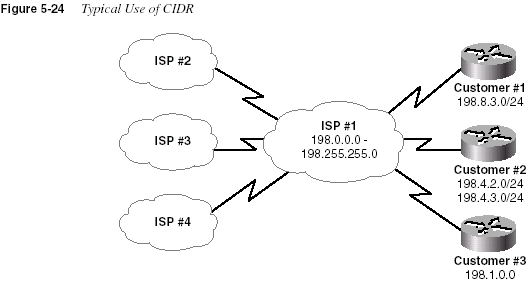
By using a routing protocol that exchanges the mask as well as the subnet/network number, a
“classless” view of the number can be attained. In other words, treat the grouping as a math
problem, ignoring the bourgeois Class A, B, and C rules. For instance, 198.0.0.0/8 (198.0.0.0,
mask 255.0.0.0) defines a set of addresses whose first 8 bits are equal. This route is advertised
by ISP #1 to the other ISPs, who need a route only to 198.0.0.0/8. In its routers, ISP #1 knows
which Class C networks are at which customer sites. This is how CIDR gives Internet routers a
much more scalable routing table, by reducing the number of entries in the tables.
Historically speaking, ISPs then found ways to use CIDR to allow better use of the IP Version
4 address space. Imagine that Customer #1 and Customer #3 need 10 and 20 IP addresses—
ever. Each customer has only a router and a single Ethernet. Each customer could register its
own Class C network, but if both did so, it would not be in the range already registered to the
ISP.
So, to help CIDR work in the Internet, ISP #1 wants its customers to use IP addresses in the
198.
x.x.x range. As a service, the ISP suggests to Customer #1 something like this: Use IPsubnet 198.8.3.16/28, with assignable addresses 198.8.17 to 198.8.30. To Customer #3, who
needs 20 addresses, ISP #1 suggests 198.8.3.32/27, with 30 assignable addresses (198.8.3.33 to
198.8.3.62). (Feel free to check the math with the IP addressing algorithms listed earlier.)
IP Addressing and Subnetting
269NOTE
The notation with the / followed by the number is a common designation on Cisco routersmeaning that the mask has that number of 1 bit. This number of 1 bit is called the
prefix. In thiscase, the mask implied with prefix /27 would be 255.255.255.224.)
The need for registered IP network numbers is reduced through CIDR. Instead of the two
customers consuming two whole Class C networks, each consumes a small portion of a single
network. The ISP gets customers to use its IP addresses in a convenient range of values, so
CIDR works well and enables the Internet to grow.
Private Addressing
A legitimate need exists for IP addresses that will never be used in the interconnected IP
networks called the Internet. So, when designing the IP addressing convention for such a
network, an organization could pick any network number(s) it wanted and use it, and all would
be well. Of course, that’s true until the organization decides to connect to the Internet—but that
will be covered later.
When IP addresses that aren’t connected to the Internet are needed, they can also be pulled from
a set of IP networks called private Internets, as defined in RFC 1918, “Address Allocation for
Private Internets” (www.ietf.org/rfc/rfc1918.txt). This RFC defines a set of networks that will
never be assigned to any organization as a registered network number. Table 5-25 shows the
private address space defined by RFC 1918.
In other words, any organization can use these network numbers. However, no organization is
allowed to advertise these networks as routes into the Internet.
The IP Version 4 address space is conserved if all organizations use private addresses in cases
for which there will never be a need for Internet connectivity. So, the dreaded day of exhausting
the registered IP Version 4 network numbers has been delayed again, in part by CIDR and in
part by private addressing.
Table 5-25
RFC 1918 Private Address SpaceRange of IP Addresses Class of Networks Number of Networks
10.0.0.0 to 10.255.255.255 A 1
172.16.0.0 to 172.31.255.255 B 16
192.168.0.0 to 192.168.255.255 C 256
270
Chapter 5: Network ProtocolsPrivate addressing’s requirement that the privately addressed hosts cannot communicate with
others through the Internet can be a particularly onerous restriction. The solution: private
addressing with the use of Network Address Translation (NAT).
Network Address Translation
Network Address Translation (NAT) is an RFC-defined function implemented in IOS that
allows a host that does not have a valid registered IP address to communicate with other hosts
through the Internet. The hosts may be using private addresses or addresses assigned to another
organization; in either case, NAT allows these addresses that are not Internet-ready to continue
to be used but still allow communication with hosts across the Internet.
NAT achieves its goal by using a valid address in some registered IP network to represent the
invalid address to the rest of the Internet. The NAT function changes the IP addresses as
necessary inside each IP packet, as shown in Figure 5-25.
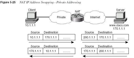
Notice that the packet’s source IP address is changed when leaving the private organization, and
the destination address is changed each time a packet is forwarded back into the private
network. Network 200.1.1.0 has been registered as a network owned by Cisco in Figure 5-25,
with address 200.1.1.1 configured as part of the NAT configuration. The NAT feature,
configured in the router labeled NAT, performs the translation. As you might expect, NAT
certainly requires more processing than simply routing the packet. Cisco does not recommend
using NAT for a large volume of different hosts.
NAT also can be used when the private organization is not using private addressing but is
instead using a network number registered to another company. (A client company of mine had
originally done just that—ironically, the company was using a network number registered to
Cabletron, which my client saw used in a presentation by an ex-Cabletron employee who then
worked at 3COM. The 3COM SE explained IP addressing using the Cabletron registered
network number; my client liked the design and took him at his word—exactly.) If one company
IP Addressing and Subnetting
271inappropriately uses the same network number that is registered appropriately to a different
company, NAT can be used, but both the source and the destination IP addresses will need to be
translated. For instance, consider Figure 5-26, with Company A using a network that is
registered to Cisco (170.1.0.0):
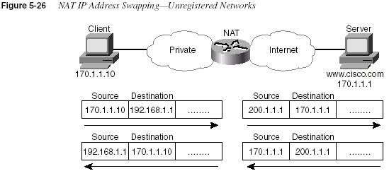
In this case, the client in Company A couldn’t send a packet to 170.1.1.1—or, at least, if it did,
the packet would never get to the real 170.1.1.1 in Cisco’s network. That is because there is a
very reasonable possibility that the private network has a route matching 170.1.1.1 in its routing
table that points to some subnet inside the private company. So, when the DNS reply comes
back past the NAT router, the DNS reply is changed by NAT so that the client in Company A
thinks www.cisco.com’s IP address is 192.168.1.1. NAT not only translates the source IP
address in outgoing packets, but it also translates the destination. Likewise, packets returning
to Company A have both the source and the destination IP addresses changed.
NAT uses terminology to define the various IP addresses used for translation. Table 5-26
summarizes the terminology and meaning.
Table 5-26
NAT Addressing TermsTerm Meaning
Value in Figure
5-26
Inside local Address of the host in the private network. When NAT is
needed, this address is typically a private address or an
address in a network registered to another organization.
170.1.1.10
Inside global The Internet (global network) view of the inside local
address. This address is in a network registered to the
company responsible for the NAT router.
200.1.1.1
Outside global The Internet (global network) view of the address of the
host correctly attached to the Internet.
170.1.1.1
continues
272
Chapter 5: Network ProtocolsIP Configuration
Configuration of TCP/IP in a Cisco router is straightforward. Table 5-27 and Table 5-28
summarize many of the most common commands used for IP configuration and verification.
Two sample network configurations, with both configuration and EXEC command output,
follow. The Cisco IOS documentation is an excellent reference for additional IP commands; the
Cisco Press book
Installing Cisco Network Devices is an excellent reference, particularly if youare not able to attend the instructor-led version of the class.
Outside local When the private company reuses a network number
registered to someone else, the outside local address
represents the outside global address in the local (private)
network. Because this address is used only in the private
organization, it can be any IP address.
192.168.1.1
Table 5-27
IP Configuration CommandsCommand Configuration Mode
ip address
ip-address mask [secondary] Interface modeip host
name [tcp-port-number] address1[
address2...address8]Global
ip route
prefix mask {next-hop-router|outputinterface}Global
ip name-server
server-address1 [[serveraddress2]…server-address6
]Global
ip domain-lookup
Globalip routing
Globalip netmask-format
{bitcount | decimal |hexadecimal
}Interface mode
ip default-network
network Globalip classless
Globalip host
name [tcp-port-number] address1[
address2…address8]Global
Table 5-26
NAT Addressing Terms (Continued)Term Meaning
Value in Figure
5-26
IP Configuration
273Collectively, Figure 5-27 and Example 5-2, Example 5-3, and Example 5-4 show three sites,
each with two serial links and one Ethernet. The following site guidelines were used when
choosing configuration details:
•
Use name servers at 10.1.1.100 and 10.1.2.100.•
Use host names from Figure 5-27.•
The router’s IP addresses are to be assigned from the last few valid IP addresses in theirattached subnets; use a mask of 255.255.255.0.
Table 5-28
IP EXEC CommandsCommand Function
show hosts
Lists all hostnames and corresponding IPaddresses
show interfaces
[type number] Lists interface statistics, including IP addressshow ip interface
[type number] Provides a detailed view of IP parameter settings,per interface
show ip interface brief
Provides a summary of all interfaces and their IPaddresses
show ip route
[subnet] Shows entire routing table, or one entry if subnetis entered
show ip arp
Displays IP ARP cachedebug ip packet
Issues log messages for each IP packetterminal ip netmask-format
{bitcount |decimal
| hexadecimal}Sets type of display for subnet masks in
showcommands
ping
Sends and receives ICMP echo messages to verifyconnectivity
trace
Sends series of UDP packets with increasing TTLvalues, to verify the current route to a host
274
Chapter 5: Network Protocols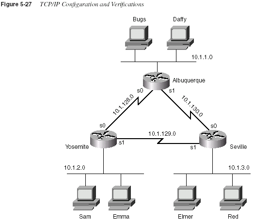
Example 5-2
Albuquerque Router Configuration and EXEC CommandsAlbuquerque#
show running-configBuilding configuration...
Current configuration:
!
version 11.2
hostname Albuquerque
!
enable secret 5 $1$skrN$z4oq6OHfB6zu1WG4P/6ZY0
!
ip name-server 10.1.1.100
ip name-server 10.1.2.100
!
interface Serial0
ip address 10.1.128.251 255.255.255.0
!
interface Serial1
ip address 10.1.130.251 255.255.255.0
IP Configuration
275!
interface Ethernet0
ip address 10.1.1.251 255.255.255.0
!
no ip classless
banner motd ^C
Should’ve taken a left turn here! This is Albuquerque... ^C
!
line con 0
password cisco
login
line aux 0
line vty 0 4
password cisco
login
!
end
Albuquerque#
show ip routeCodes: C - connected, S - static, I - IGRP, R - RIP, M - mobile, B - BGP
D - EIGRP, EX - EIGRP external, O - OSPF, IA - OSPF inter area
N1 - OSPF NSSA external type 1, N2 - OSPF NSSA external type 2
E1 - OSPF external type 1, E2 - OSPF external type 2, E - EGP
i - IS-IS, L1 - IS-IS level-1, L2 - IS-IS level-2, * - candidate default
U - per-user static route, o - ODR
Gateway of last resort is not set
10.0.0.0/24 is subnetted, 3 subnets
C 10.1.1.0 is directly connected, Ethernet0
C 10.1.130.0 is directly connected, Serial1
C 10.1.128.0 is directly connected, Serial0
Albuquerque#
terminal ip netmask-format decimalAlbuquerque#
show ip routeCodes: C - connected, S - static, I - IGRP, R - RIP, M - mobile, B - BGP
D - EIGRP, EX - EIGRP external, O - OSPF, IA - OSPF inter area
N1 - OSPF NSSA external type 1, N2 - OSPF NSSA external type 2
E1 - OSPF external type 1, E2 - OSPF external type 2, E - EGP
i - IS-IS, L1 - IS-IS level-1, L2 - IS-IS level-2, * - candidate default
U - per-user static route, o - ODR
Gateway of last resort is not set
10.0.0.0 255.255.255.0 is subnetted, 3 subnets
C 10.1.1.0 is directly connected, Ethernet0
C 10.1.130.0 is directly connected, Serial1
C 10.1.128.0 is directly connected, Serial0
Albuquerque#
Example 5-2
Albuquerque Router Configuration and EXEC Commands (Continued)276
Chapter 5: Network ProtocolsExample 5-3
Yosemite Router Configuration and EXEC CommandsYosemite#
show running-configBuilding configuration...
Current configuration:
!
version 11.2
hostname Yosemite
!
enable secret 5 $1$.Iud$7uHqWzDYgvJN09V7HSkLZ/
!
ip name-server 10.1.1.100
ip name-server 10.1.2.100
!
interface Serial0
ip address 10.1.128.252 255.255.255.0
no fair-queue
!
interface Serial1
ip address 10.1.129.252 255.255.255.0
!
interface Ethernet0
ip address 10.1.2.252 255.255.255.0
!
no ip classless
banner motd ^C
This is the Rootin-est Tootin-est Router in these here parts! ^C
!
line con 0
password cisco
login
line aux 0
line vty 0 4
password cisco
login
!
end
Yosemite#
show ip interface briefInterface IP-Address OK? Method Status Protocol
Serial0 10.1.128.252 YES manual up up
Serial1 10.1.129.252 YES manual up up
Ethernet0 10.1.2.252 YES manual up up
Yosemite#
IP Configuration
277Example 5-4
Seville Router Configuration and EXEC CommandsSeville#
show running-configBuilding configuration...
Current configuration:
!
version 11.2
!
hostname Seville
!
enable secret 5 $1$ZvR/$Gpk5a5K5vTVpotd3KUygA1
!
ip name-server 10.1.1.100
ip name-server 10.1.2.100
!
interface Serial0
ip address 10.1.130.253 255.255.255.0
no fair-queue
!
interface Serial1
ip address 10.1.129.253 255.255.255.0
!
Ethernet0
ip address 10.1.3.253 255.255.255.0
!
no ip classless
banner motd ^C
Take a little off the top, Wabbit! (Elmer) ^C
!
line con 0
password cisco
login
line aux 0
line vty 0 4
password cisco
login
!
end
Seville#
show ip routeCodes: C - connected, S - static, I - IGRP, R - RIP, M - mobile, B - BGP
D - EIGRP, EX - EIGRP external, O - OSPF, IA - OSPF inter area
N1 - OSPF NSSA external type 1, N2 - OSPF NSSA external type 2
E1 - OSPF external type 1, E2 - OSPF external type 2, E - EGP
i - IS-IS, L1 - IS-IS level-1, L2 - IS-IS level-2, * - candidate default
U - per-user static route, o - ODR
Gateway of last resort is not set
10.0.0.0/24 is subnetted, 3 subnets
C 10.1.3.0 is directly connected, Ethernet0
continues
278
Chapter 5: Network ProtocolsC 10.1.130.0 is directly connected, Serial0
C 10.1.129.0 is directly connected, Serial1
Seville#
show ip interface serial 1Serial1 is up, line protocol is up
Internet address is 10.1.129.253/24
Broadcast address is 255.255.255.255
Address determined by nonvolatile memory
MTU is 1500 bytes
Helper address is not set
Directed broadcast forwarding is disabled
Outgoing access list is not set
Inbound access list is not set
Proxy ARP is enabled
Security level is default
Split horizon is enabled
ICMP redirects are always sent
ICMP unreachables are always sent
ICMP mask replies are never sent
IP fast switching is enabled
IP fast switching on the same interface is enabled
IP Fast switching turbo vector
IP multicast fast switching is enabled
IP multicast distributed fast switching is disabled
Router Discovery is disabled
IP output packet accounting is disabled
IP access violation accounting is disabled
TCP/IP header compression is disabled
RTP/IP header compression is disabled
Probe proxy name replies are disabled
Policy routing is disabled
Network address translation is disabled
Web Cache Redirect is disabled
BGP Policy Mapping is disabled
Seville#
show interface serial 0Serial0 is up, line protocol is up
Hardware is HD64570
Internet address is 10.1.130.253/24
MTU 1500 bytes, BW 1544 Kbit, DLY 20000 usec, rely 255/255, load 1/255
Encapsulation HDLC, loopback not set, keepalive set (10 sec)
Last input 00:00:05, output 00:00:04, output hang never
Last clearing of “show interface” counters never
Queuing strategy: fifo
Output queue 0/40, 0 drops; input queue 0/75, 0 drops
5 minute input rate 0 bits/sec, 0 packets/sec
5 minute output rate 0 bits/sec, 0 packets/sec
273 packets input, 18621 bytes, 0 no buffer
Received 215 broadcasts, 0 runts, 0 giants, 0 throttles
0 input errors, 0 CRC, 0 frame, 0 overrun, 0 ignored, 0 abort
309 packets output, 20175 bytes, 0 underruns
0 output errors, 0 collisions, 23 interface resets
Example 5-4
Seville Router Configuration and EXEC Commands (Continued)IP Configuration
279Notice that the configuration matches the output of the
show interface, show ip interface, andshow interface ip brief
commands. For instance, in Example 5-3, the IP addresses in theconfiguration match the output of
show ip interface brief. If these details did not match,one common oversight is that you are looking at the configuration in NVRAM, not in RAM.
Make sure to use the
show running-config or write terminal commands to see the activeconfiguration.
The subnet mask in the output of
show commands is encoded by numbering the network andsubnet bits. For example, 10.1.4.0/24 means 24 network and subnet bits, leaving 8 host bits with
this subnetting scheme. The
terminal ip netmask command can be used to change thisformatting, as seen in Example 5-2.
Example 5-4 shows the ARP cache generated by the
show ip arp output. The first entry showsthe IP address and MAC address of another host on the Ethernet. The timer value of 0 implies
that the entry is very fresh—the value grows with disuse. One entry is shown for the router’s
Ethernet interface itself, which never times out of the ARP table.
The
debug ip packet output in Example 5-4 lists one entry per IP packet sent and received. Thiscommand is a very dangerous command—it could crash almost any production router due to
the added overhead of processing the debug messages. Notice that the output shows both the
source and destination IP addresses.
0 output buffer failures, 0 output buffers swapped out
0 carrier transitions
DCD=up DSR=up DTR=up RTS=up CTS=up
Seville#
show ip arpProtocol Address Age (min) Hardware Addr Type Interface
Internet 10.1.3.102 0 0060.978b.1301 ARPA Ethernet0
Internet 10.1.3.253 - 0000.0c3e.5183 ARPA Ethernet0
Seville#
debug ip packetIP packet debugging is on
Seville#
ping 10.1.130.251Type escape sequence to abort.
Sending 5, 100-byte ICMP Echos to 10.1.130.251, timeout is 2 seconds:
!!!!!
Success rate is 100 percent (5/5), round-trip min/avg/max = 80/81/84 ms
Seville#
00:09:38: IP: s=10.1.130.251 (local), d=10.1.130.251 (Serial1), len 100, sending
00:09:38: IP: s=10.1.130.251 (Serial1), d=10.1.130.253 (Serial1), len 100, rcvd 3
00:09:38: IP: s=10.1.130.253 (local), d=10.1.130.251 (Serial1), len 100, sending
00:09:38: IP: s=10.1.130.251 (Serial1), d=10.1.130.253 (Serial1), len 100, rcvd 3
00:09:38: IP: s=10.1.130.253 (local), d=10.1.130.251 (Serial1), len 100, sending
00:09:38: IP: s=10.1.130.251 (Serial1), d=10.1.130.253 (Serial1), len 100, rcvd 3
00:09:38: IP: s=10.1.130.253 (local), d=10.1.130.251 (Serial1), len 100, sending
00:09:38: IP: s=10.1.130.251 (Serial1), d=10.1.130.253 (Serial1), len 100, rcvd 3
00:09:38: IP: s=10.1.130.253 (local), d=10.1.130.251 (Serial1), len 100, sending
00:09:38: IP: s=10.1.130.251 (Serial1), d=10.1.130.253 (Serial1), len 100, rcvd 3
Seville#
Example 5-4
Seville Router Configuration and EXEC Commands (Continued)280
Chapter 5: Network ProtocolsThe routing table in Example 5-4 does not list all subnets because the routing protocol
configuration has not been added. Notice that the
show ip route commands list routes to thedirectly attached subnets, but no others. The
ip route commands in Example 5-5 have beenadded to Albuquerque. Example 5-6 and Example 5-7 contain
show commands executed afterthe new configuration was added.
Example 5-5
Static Routes Added to Albuquerqueip route 10.1.2.0 255.255.255.0 10.1.128.252
ip route 10.1.3.0 255.255.255.0 10.1.130.253
Example 5-6
Albuquerque Router EXEC Commands, After Adding Static Routes for 10.1.2.0 and 10.1.3.0Albuquerque#
show ip routeCodes: C - connected, S - static, I - IGRP, R - RIP, M - mobile, B - BGP
D - EIGRP, EX - EIGRP external, O - OSPF, IA - OSPF inter area
N1 - OSPF NSSA external type 1, N2 - OSPF NSSA external type 2
E1 - OSPF external type 1, E2 - OSPF external type 2, E - EGP
i - IS-IS, L1 - IS-IS level-1, L2 - IS-IS level-2, * - candidate default
U - per-user static route, o - ODR
Gateway of last resort is not set
10.0.0.0/24 is subnetted, 5 subnets
S 10.1.3.0 [1/0] via 10.1.130.253
S 10.1.2.0 [1/0] via 10.1.128.252
C 10.1.1.0 is directly connected, Ethernet0
C 10.1.130.0 is directly connected, Serial1
C 10.1.128.0 is directly connected, Serial0
Albuquerque#
ping 10.1.128.252Type escape sequence to abort.
Sending 5, 100-byte ICMP Echos to 10.1.128.252, timeout is 2 seconds:
!!!!!
Success rate is 100 percent (5/5), round-trip min/avg/max = 4/4/8 ms
! Note: the following extended ping command will result in some debug messages
! on Yosemite in Example 5-7.
Albuquerque#
pingProtocol [ip]:
Target IP address:
10.1.2.252Repeat count [5]:
Datagram size [100]:
Timeout in seconds [2]:
Extended commands [n]:
ySource address or interface:
10.1.1.251Type of service [0]:
Set DF bit in IP header? [no]:
Validate reply data? [no]:
Data pattern [0xABCD]:
Loose, Strict, Record, Timestamp, Verbose[none]:
Sweep range of sizes [n]:
Type escape sequence to abort.
IP Configuration
281Sending 5, 100-byte ICMP Echos to 10.1.2.252, timeout is 2 seconds:
. . . . .
Success rate is 0 percent (0/5)
Albuquerque#
Example 5-7
show ip route on Yosemite, After Adding Static Routes to AlbuquerqueYosemite#
show ip routeCodes: C - connected, S - static, I - IGRP, R - RIP, M - mobile, B - BGP
D - EIGRP, EX - EIGRP external, O - OSPF, IA - OSPF inter area
N1 - OSPF NSSA external type 1, N2 - OSPF NSSA external type 2
E1 - OSPF external type 1, E2 - OSPF external type 2, E - EGP
i - IS-IS, L1 - IS-IS level-1, L2 - IS-IS level-2, * - candidate default
U - per-user static route, o - ODR
Gateway of last resort is not set
10.0.0.0/24 is subnetted, 3 subnets
C 10.1.2.0 is directly connected, Ethernet0
C 10.1.129.0 is directly connected, Serial1
C 10.1.128.0 is directly connected, Serial0
Yosemite#
ping 10.1.128.251Type escape sequence to abort.
Sending 5, 100-byte ICMP Echos to 10.1.128.251, timeout is 2 seconds:
!!!!!
Success rate is 100 percent (5/5), round-trip min/avg/max = 4/4/8 ms
Yosemite#
ping 10.1.1.251Type escape sequence to abort.
Sending 5, 100-byte ICMP Echos to 10.1.1.251, timeout is 2 seconds:
.....
Success rate is 0 percent (0/5)
Yosemite#
debug ip icmpICMP packet debugging is on
Yosemite#
Yosemite#
show debugGeneric IP:
ICMP packet debugging is on
Yosemite#
!NOTE: the following debug messages are a result of the extended
ping!command issued on Albuquerque in Example 5-6;
!these messages are generated by Yosemite!
ICMP: echo reply sent, src 10.1.2.252, dst 10.1.1.251
ICMP: echo reply sent, src 10.1.2.252, dst 10.1.1.251
ICMP: echo reply sent, src 10.1.2.252, dst 10.1.1.251
ICMP: echo reply sent, src 10.1.2.252, dst 10.1.1.251
ICMP: echo reply sent, src 10.1.2.252, dst 10.1.1.251
Example 5-6
Albuquerque Router EXEC Commands, After Adding Static Routes for 10.1.2.0 and 10.1.3.0 (Continued)282
Chapter 5: Network ProtocolsTwo subtleties of the
ping command are used in these two example console dialogs ofExamples 5-6 and 5-7:
•
Cisco ping commands use the output interface’s IP address as the source address of thepacket, unless otherwise specified in an extended
ping. The first ping in Example 5-6 usesa source of 10.1.128.251; the extended
ping uses the source address shown (10.1.1.251).•
ICMP Echo Reply messages (ping responses) reverse the IP addresses used in the ICMPEcho Request to which it is responding.
The extended version of the
ping command can be used to more fully refine the underlyingcause of the problem. In fact, when a
ping from a router works but a ping from a host does not,the extended
ping could help in re-creating the problem without needing to work with the enduser on the phone. For instance, the extended
ping command on Albuquerque sent an EchoRequest from 10.1.1.251 (Albuquerque’s Ethernet) to 10.1.2.252 (Yosemite’s Ethernet); no
response was received by Albuquerque. Normally, the echoes are sourced from the IP address
of the outgoing interface; with the use of the extended
ping source address option, the sourceIP address of the echo packet can be changed. It appears that the ICMP Echo Requests were
received by Yosemite because the debug messages on Yosemite imply that it sent ICMP Echo
Replies back to 10.1.1.251. Somewhere between Yosemite creating the ICMP echo replies and
Albuquerque receiving them, a problem occurred.
An examination of the steps after the echo replies were created by Yosemite is needed to
understand the problem in this example. ICMP asks the IP software in Yosemite to deliver the
packets. The IP code performs IP routing table lookup to find the correct route for these packets,
whose destination is 10.1.1.251. However, the
show ip route command output in Example 5-7shows that Yosemite has no route to subnet 10.1.1.0. It seems that Yosemite created the Echo
Reply messages but failed to send them because it has no route to 10.1.1.0/24. This is just one
example in which the route in one direction is working fine, but the route in the reverse direction
is not.
Other options for extended
ping are also quite useful. The Don’t Fragment (DF) bit can be set,along with the amount of data to send in the echo, so that the MTU for the entire route can be
discovered through experimentation. Echo packets that are too large to pass over a link due to
MTU restrictions will be discarded because the DF bit is set. The timeout value can be set so
that the
ping command will wait longer than the default 2 seconds before thinking that an echowill receive a reply. Furthermore, not only can a single size for the ICMP Echo be set, but a
range of sizes can be used to give a more realistic set of packets.
One key to troubleshooting with the
ping command is understanding the various codes thecommand uses to signify the various responses it can receive. Table 5-29 lists the various codes
that the Cisco IOS
ping command can supply.IP Configuration
283Using Secondary Addresses
As a CCNA, Cisco expects you to be comfortable and familiar with IP address planning issues.
One such issue involves what to do when there are no more unassigned IP addresses in a subnet.
One alternative solution is to change the mask used on that subnet, making the existing subnet
larger. However, changing the mask could cause an overlap. For example, if 10.1.4.0/24 is
running out of addresses and you make a change to mask 255.255.254.0 (9 host bits, 23
network/subnet bits), an overlap can occur. 10.1.4.0/23 includes addresses 10.1.4.0 to
10.1.5.255; this is indeed an overlap with subnet 10.1.5.0/24. If subnet 10.1.5.0/24 already
exists, using 10.1.4.0/23 would not work. Another alternative for continued growth is to place
all the existing addresses in the mostly full subnet in another larger subnet. There must be a
valid subnet number that is unassigned, that does not create an overlap, and that is larger than
the old subnet. However, this solution causes administrative effort to change the IP addresses.
In either case, both solutions that do not use secondary addressing imply a strategy of using
different masks in different parts of the network. Use of these different masks is called variablelength
subnet masking (VLSM), which brings up another set of complex routing protocol
issues.
This same issue can be solved by the use of IP secondary addressing. Secondary addressing
uses multiple subnets on the same data link. Secondary IP addressing is simple in concept.
Because more than one subnet is used on the same medium, the router needs to have more than
one IP address on the interface attached to that medium. For example, Figure 5-27 has subnet
10.1.2.0/24; assume that the subnet has all IP addresses assigned. Assuming secondary
addressing to be the chosen solution, subnet 10.1.7.0/24 could also be used on the same
Ethernet. Example 5-8 shows the configuration for secondary IP addressing on Yosemite.
Table 5-29
Explanation of the Codes the ping Command Receives in Response to Its ICMP Echo Requestping Command Code Explanation
! ICMP Echo Reply received
. Nothing received
U ICMP unreachable (destination) received
N ICMP unreachable (network) received
P ICMP unreachable (port) received
Q ICMP source quench received
M ICMP can’t fragment message received
? Unknown packet received
284
Chapter 5: Network ProtocolsThe router has routes to subnets 10.1.2.0/24 and 10.1.7.0/24, so it can forward packets to each
subnet. The router also can receive packets from hosts in one subnet and can forward the
packets to the other subnet using the same interface.
IP Addressing with Frame Relay Subinterfaces
Frame Relay configuration can be accomplished with or without the use of subinterfaces. If
subinterfaces are not used, then all router interfaces attached to this same Frame Relay cloud
should be configured with IP addresses in the same subnet. In other words, treat the Frame
Relay cloud as any other multiaccess medium (such as a LAN). However, Frame Relay
configuration without subinterfaces introduces some routing protocol issues when there is not
a full mesh of virtual circuits (VCs) between each pair of routers. Subinterfaces allow distance
vector routing protocols to work well because individual VCs can be considered as separate
interfaces. This allows the routing protocol to maintain its split-horizon feature to defeat routing
loops.
Example 5-8
Secondary IP Addressing Configuration and show ip route Command on Yosemite! Excerpt from
show running-config follows...Hostname Yosemite
ip domain-lookup
ip name-server 10.1.1.100 10.1.2.100
interface ethernet 0
ip address 10.1.7.252 255.255.255.0 secondary
ip address 10.1.2.252 255.255.255.0
interface serial 0
ip address 10.1.128.252 255.255.255.0
interface serial 1
ip address 10.1.129.252 255.255.255.0
Yosemite#
show ip routeCodes: C - connected, S - static, I - IGRP, R - RIP, M - mobile, B - BGP
D - EIGRP, EX - EIGRP external, O - OSPF, IA - OSPF inter area
N1 - OSPF NSSA external type 1, N2 - OSPF NSSA external type 2
E1 - OSPF external type 1, E2 - OSPF external type 2, E - EGP
i - IS-IS, L1 - IS-IS level-1, L2 - IS-IS level-2, * - candidate default
U - per-user static route, o - ODR
Gateway of last resort is not set
10.0.0.0/24 is subnetted, 4 subnets
C 10.1.2.0 is directly connected, Ethernet0
C 10.1.7.0 is directly connected, Ethernet0
C 10.1.129.0 is directly connected, Serial1
C 10.1.128.0 is directly connected, Serial0
Yosemite#
IP Configuration
285Chapter 8, “WAN Protocols and Design,” covers issues relating to the design choices of when
to use subinterfaces and what type to use. This current section discusses how to assign IP
addresses after those choices are made.
The use of subinterfaces and the type of subinterface implies the number of subnets used for
Frame Relay. A point-to-point subinterface terminates one VC and has an IP address assigned
to it; the router on the other end of the VC uses an IP address in the same subnet. These two IP
addresses are the only two addresses in the subnet. Each separate instance of a pair of routers
on opposing ends of a VC, each with a point-to-point subinterface configuration, implies the
use of yet another subnet, with only two host addresses in the subnet.
The use of no subinterfaces and the use of multipoint subinterfaces are identical from the
perspective of how to assign IP addresses. Multipoint subinterfaces are used when multiple VCs
terminate at the subinterface; this subinterface, along with all subinterfaces on other routers at
the other end of these VCs, are configured to be in the same subnet. With no subinterfaces used,
all the routers attached to the Frame Relay network are also considered to be in the same subnet.
Most often, point-to-point subinterfaces are used when a partial mesh of VCs is used.
Conversely, multipoint subnets are used when a full mesh is used. However, both types of
subinterface are allowed in the same router. Figure 5-28 shows a Frame Relay configuration
requiring three different subnets over a Frame Relay cloud.
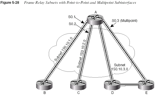
286
Chapter 5: Network ProtocolsExample 5-9, Example 5-10, and Example 5-11 show the configurations on Routers A, B, and
E, respectively.
For a more complete review of the concepts behind IP addressing over Frame Relay, refer to
Chapter 8.
Example 5-9
Router A Configurationhostname routerA
interface serial 0
encapsulation frame-relay
!
interface serial 0.1 point-to-point
ip address 150.10.1.250 255.255.255.0
frame-relay interface-dlci 40
description this is for the VC to site B
!
interface serial 0.2 point-to-point
ip address 150.10.2.250 255.255.255.0
frame-relay interface-dlci 41
description this is for the VC to site C
!
interface serial 0.3 multipoint
ip address 150.10.3.250 255.255.255.0
interface-dlci 42
interface-dlci 43
description this is for the VC’s to sites D and E
Example 5-10
Router B Configurationhostname routerB
!
interface serial 0
encapsulation frame-relay
!
interface serial 0.1 point-to-point
ip address 150.10.1.251 255.255.255.0
frame-relay interface-dlci 44
description this is for the VC to site A
Example 5-11
Router E Configurationhostname routerE
!
interface serial 0
encapsulation frame-relay
!
interface serial 0.3 multipoint
ip address 150.10.3.254 255.255.255.0
frame-relay interface-dlci 44
description this is for the VC to site A
IP Configuration
287MTU and Fragmentation
The maximum transmission unit (MTU) is a concept that implies the largest Layer 3 packet that
can be forwarded out an interface. The maximum MTU value allowed is based on the data link
protocol; essentially, the maximum size of the data portion of the data link frame (where the
packet is placed) is the maximum setting for the MTU on an interface. The default MTU value
is 1500.
If an interface’s MTU is smaller than a packet that must be forwarded, fragmentation is
performed by the router. Fragmentation is the process of simply breaking the packet into
smaller packets, each of which is less than or equal to the MTU value. For instance, consider
Figure 5-29, with a point-to-point serial link whose MTU has been lowered to 1000.
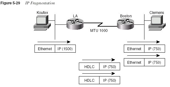
As Figure 5-29 illustrates, Koufax threw a 1500-byte packet toward Router LA. LA removed
the Ethernet header but could not forward the packet because it was 1500 bytes and the HDLC
link supported only an MTU of 1000. So, LA fragmented the original packet into two packets.
After forwarding the two packets, Boston receives the packets and does not reassemble them—
reassembly is done by the endpoint host, which in this case is Clemens.
The IP header contains fields useful for reassembly to the fragments into the original packet.
The IP header includes an ID value that is the same in each fragmented packet, as well as an
offset value that defines which part of the original packet is held in each fragment. So,
fragmented packets arriving out of order can be identified as part of the same original packet
and can be reassembled into the correct order using the offset field in each fragment.
Two configuration commands can be used to change the IP MTU size on an interface: the
mtuinterface subcommand and the
ip mtu interface subcommand. The mtu command sets theMTU for all Layer 3 protocols; unless there is a need to vary the setting per Layer 3 protocol,
288
Chapter 5: Network Protocolsthis command is preferred. If a different setting is desired for IP, the
ip mtu command sets thevalue used for IP.
A few nuances relate to the two MTU-setting commands. If both are configured on an interface,
then the IP MTU setting takes precedence on the interface. However, if the
mtu command isconfigured after the
ip mtu is configured, the ip mtu value is reset to the same value as that ofthe
mtu command. So, care must be taken when changing these values.IP Naming Commands and Telnet
Names are never important to the process of routing IP packets. However, most human users
prefer to use names instead of IP addresses, for obvious reasons. So, the process of using
names—and, most frequently, using a Domain Name System (DNS) to identify the IP address
that corresponds to a name—is important for end users.
Router and switch administrators like to use names in many cases, for the same reason that end
users like to use names. When the administrator uses a PC or workstation, that person can open
up a variety of windows and Telnet to various routers and switches. This short section is not
concerned with naming in that case.
When a router or switch administrator is logged in to the router or switch, a variety of
commands are available. Particularly for the
trace, ping, and telnet commands, one keyparameter is the IP address or host name of that with which you want to trace, ping, or telnet.
This section describes the use of host names on an IOS-based device. Along the way, some
nuances of the use of Telnet are covered.
The IOS can use statically configured names as well as refer to one or more DNSs. Example
5-12 shows some names statically configured, with configuration pointing to two different
DNSs.
Example 5-12
IP Naming Configuration and show ip host Commandhostname Cooperstown
!
ip host Mays 10.1.1.1
ip host Aaron 10.2.2.2
ip host Mantle 10.3.3.3
!
ip domain-name lacidar.com
ip name-server 10.1.1.200 10.2.2.200
ip domain-lookup
Seville#
show hostsDefault domain is lacidar.com
Name/address lookup uses static mappings
Host Flags Age Type Address(es)
Mays (perm, OK) 0 IP 10.1.1.1
Aaron (perm, OK) 0 IP 10.2.2.2
Mantle (perm, OK) 0 IP 10.3.3.3
Seville#
IP Configuration
289Three names are statically configured in this case—Mays, Aaron, and Mantle. When logged
into Cooperstown, any command referring to Mays, Aaron, or Mantle will resolve into the IP
addresses shown in the
ip host command.DNS configuration is shown toward the end of the configuration. For names that do not include
the full domain name, the
ip domain-name command defines the domain name that should beassumed by the router. The IP addresses of the name servers are shown in the
ip name-servercommand. Up to six DNSs can be listed; they are searched for each request sequentially based
on the order in the command. Finally, the
ip domain-lookup command enables the IOS to aska name-server. IP domain-lookup is the default;
no ip domain-lookup disables the DNS clientfunction.
The name Cooperstown in the
hostname command is shown to make a point that it is not adefinition that creates a correlation between a name and an IP address. The
hostname commandtells this device what its own name is; any command referring to a host name and with
Cooperstown typed as the host name would need either an
ip host command or a DNSresolution for Cooperstown for the command to work.
The
show ip host command lists the static entries, in addition to any entries learned from a DNSrequest. Only the three static entries were in the table, in this case. The term
perm in the outputimplies that the entry is static.
Telnet on the IOS
The
telnet IOS EXEC command can be particularly useful when working with more than onerouter or switch at the same time. If you prefer, you could open more windows on your desktop
and Telnet to the various routers and switches. However, if you log in to one router and then
want to Telnet to others, this subsection provides you with some interesting capabilities of the
IOS Telnet client and server.
Each IOS runs a Telnet server automatically. Just like other Telnet servers, it listens on port 23.
The
telnet EXEC command is a Telnet client, which can be used to Telnet to many otherdevices, not just another router or switch. So, many of the same assumptions you make about
Telnet are true for the IOS-based Telnet client and server.
The convenient use of the suspend function of the Telnet client is one of the best features of the
Telnet client. For this discussion, you will need to refer to the network diagram in Figure 5-30.
290
Chapter 5: Network Protocols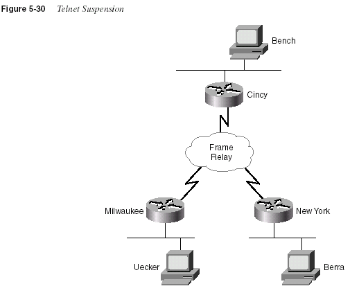
In the figure, the router administrator is using Bench to Telnet into the Cincy router. Once in
Cincy, the user Telnets to Milwaukee. Once in Milwaukee, the user suspends the Telnet by
pressing Ctrl+Shift+6, followed by pressing the letter x. The user then Telnets to NewYork and
again suspends the connection. Example 5-13 shows an example output:
Example 5-13
Telnet SuspensionsCincy#
telnet milwaukeeTrying Milwaukee (10.1.4.252)... Open
User Access Verification
Password:
Milwaukee>
Milwaukee>
Milwaukee>
(Note: User pressed CTL-SHIFT-6, then x)
Cincy#
telnet NewYorkTrying NewYork (10.1.6.253)... Open
User Access Verification
IP Configuration
291Example 5-13 begins with the Cincy command prompt that would be seen in Bench’s Telnet
window because the user at Bench Telnetted into Cincy first. After Telnetting to Milwaukee, the
Telnet connection was suspended. Then, after Telnetting to NewYork, that connection was
suspended. The two connections can be suspended or resumed easily. The
resume commandcan be used to resume the connections; however, the
resume command requires a connectionID, which is shown in the
show connections command. (The where command provides thesame output.)
Password:
NewYork>
NewYork>
NewYork>
NewYork>
(Note: User pressed CTL-SHIFT-6, then x)
Cincy#
show sessionsConn Host Address Byte Idle Conn Name
1 milwaukee 10.1.4.252 0 0 milwaukee
* 2 NewYork 10.1.6.253 0 0 NewYork
Cincy#
whereConn Host Address Byte Idle Conn Name
1 milwaukee 10.1.4.252 0 0 milwaukee
* 2 NewYork 10.1.6.253 0 0 NewYork
Cincy#
resume 1[Resuming connection 1 to milwaukee ... ]
Milwaukee>
Milwaukee>
Milwaukee>
(Note: User pressed CTL-SHIFT-6, then x)
Cincy#
[Resuming connection 1 to milwaukee ... ]
(Note: User, when at Cincy, just pressed return)
Milwaukee>
Milwaukee>
Milwaukee>
(Note: User pressed CTL-SHIFT-6, then x)
Cincy#
disconnect 1Closing connection to milwaukee [confirm]
Cincy#
[Resuming connection 2 to NewYork ... ]
(Note: User, when at Cincy, just pressed return)
NewYork>
NewYork>
NewYork>
(Note: User pressed CTL-SHIFT-6, then x)
Cincy#
disconnect 2Closing connection to NewYork [confirm]
Cincy#
Example 5-13
Telnet Suspensions (Continued)292
Chapter 5: Network ProtocolsThe interesting and potentially dangerous nuance here is that if a Telnet session is suspended
and you simply press
Enter, the IOS resumes the connection to the most recently suspendedTelnet connection
. That is fine, until you realize how much you tend to press the Enter keyoccasionally to clear some of the clutter from the screen. With a suspended Telnet connection,
you also just happened to reconnect to another router. This is particularly dangerous when you
are changing the configuration or using potentially damaging EXEC commands—be careful
about what router you are actually using when you type the command.
Default Routes and the ip classless Command
Default route processing can be useful in several situations. Default route processing is a
general term that refers to the choices that the router can make when no match exists between
the routing table and the destination address of a packet. Without any default routes, a packet
whose destination is not matched in the routing table is discarded.
Figure 5-31 shows a typical case in which some form of default route would be useful. R1, R2,
and R3 are connected to the rest of this network only via R1’s Token Ring interface. If R2 and
R3 could forward packets meant for unknown destinations to R1, and if R1 knew to send them
to router Dist1, then all three routers could deliver packets to the rest of the network without
actually needing to route to all the other networks subnets in their routing tables.
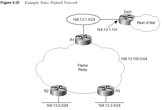
IP Configuration
293By coding a default route on R1 that points to router Dist1 in Figure 5-31, the default routing
can be accomplished. R1 advertises the default route to R2 and R3. Examples 5-14 and 5-15,
along with Figure 5-31, show an example of a default route on R1.
Example 5-14
R1 Static Default Route Configuration and Routing TableR1(config)#
ip route 0.0.0.0 0.0.0.0 168.13.1.101R1#
show ip routeCodes: C - connected, S - static, I - IGRP, R - RIP, M - mobile, B - BGP
D - EIGRP, EX - EIGRP external, O - OSPF, IA - OSPF inter area
N1 - OSPF NSSA external type 1, N2 - OSPF NSSA external type 2
E1 - OSPF external type 1, E2 - OSPF external type 2, E - EGP
i - IS-IS, L1 - IS-IS level-1, L2 - IS-IS level-2, * - candidate default
U - per-user static route, o - ODR
Gateway of last resort is 168.13.1.101 to network 0.0.0.0
168.13.0.0/24 is subnetted, 4 subnets
C 168.13.1.0 is directly connected, TokenRing0
R 168.13.3.0 [120/1] via 168.13.100.3, 00:00:05, Serial0.1
R 168.13.2.0 [120/1] via 168.13.100.2, 00:00:21, Serial0.1
C 168.13.100.0 is directly connected, Serial0.1
S* 0.0.0.0/0 [1/0] via 168.13.1.101
R1#
Example 5-15
R3—Nuances with Successful Use of Static Route on R1R3#
show ip routeCodes: C - connected, S - static, I - IGRP, R - RIP, M - mobile, B - BGP
D - EIGRP, EX - EIGRP external, O - OSPF, IA - OSPF inter area
N1 - OSPF NSSA external type 1, N2 - OSPF NSSA external type 2
E1 - OSPF external type 1, E2 - OSPF external type 2, E - EGP
i - IS-IS, L1 - IS-IS level-1, L2 - IS-IS level-2, * - candidate default
U - per-user static route, o - ODR
Gateway of last resort is 168.13.100.1 to network 0.0.0.0
168.13.0.0/24 is subnetted, 4 subnets
R 168.13.1.0 [120/1] via 168.13.100.1, 00:00:13, Serial0.1
C 168.13.3.0 is directly connected, Ethernet0
R 168.13.2.0 [120/1] via 168.13.100.2, 00:00:06, Serial0.1
C 168.13.100.0 is directly connected, Serial0.1
R* 0.0.0.0/0 [120/1] via 168.13.100.1, 00:00:14, Serial0.1
R3#
ping 168.13.200.1Type escape sequence to abort.
Sending 5, 100-byte ICMP Echos to 168.13.200.1, timeout is 2 seconds:
.....
Success rate is 0 percent (0/5)
R3#
R3#
conf tEnter configuration commands, one per line. End with CNTL/Z.
continues
294
Chapter 5: Network ProtocolsThe default route shows up in the routing tables in R1, R2, and R3. The default route is defined
with a static
ip route command, with destination 0.0.0.0, mask 0.0.0.0. This route matches alldestinations.
The default route on R3 is not used, however, in the first
ping on R3. This is because the no ipclassless
command was configured on R3 (not shown). This causes R3’s matching logic tomean “best match in the same network as the destination of the packet.” In other words, the
destination (168.13.200.1) is in Class B network 168.13.0.0. Because there is no match between
168.13.200.1 and the known subnets of 168.13.0.0, then the destination is not matched by R3
and the packet is not forwarded. When
ip classless is added to R3 (it was already configured onR1), the routing logic is changed to “best match in the entire routing table.” In other words, the
router ignores class rules when routing. Because the route to 0.0.0.0 is a match for any
destination, that route is used and the second
ping in Example 5-15 succeeds.The gateway of last resort, highlighted in the
show ip route command output, sounds like apretty desperate feature. There are worse things than having to discard a packet in a router, but
this phrase simply references the current default route. It is possible that several default routes
have been configured and then distributed with a routing protocol; the Gateway of last resort is
the currently used default on a particular router. Be careful—multiple defaults can cause a
routing loop.
Another style of configuration for the default route uses the
ip default-network command. Thiscommand is used most typically when you want to reach other Class A, B, or C networks by
default, but all the subnets of your own network are expected to be in your own routing tables.
For instance, imagine that the cloud next to Dist1 in Figure 5-31 has subnets of network 10.0.0.0
in it, as well as other networks. (Dist1 could be an ISP router.) The network in Figure 5-31 is
still in use, but instead of the
ip route 0.0.0.0 0.0.0.0 168.13.1.101 command, the ip defaultnetwork10.0.0.0
command is used on R1. R1 uses its route to network 10.0.0.0 as its defaultand advertises this route as a default route to other routers. Examples 5-16 and 5-17 show
several details on R1 and R3.
R3(config)#
ip classlessR3(config)#
^ZR3#
ping 168.13.200.1Type escape sequence to abort.
Sending 5, 100-byte ICMP Echos to 168.13.200.1, timeout is 2 seconds:
!!!!!
Success rate is 100 percent (5/5), round-trip min/avg/max = 80/88/112 ms
R3#
Example 5-15
R3—Nuances with Successful Use of Static Route on R1 (Continued)IP Configuration
295Example 5-16
R1’s Use of the ip default-network CommandR1#
show ip routeCodes: C - connected, S - static, I - IGRP, R - RIP, M - mobile, B - BGP
D - EIGRP, EX - EIGRP external, O - OSPF, IA - OSPF inter area
N1 - OSPF NSSA external type 1, N2 - OSPF NSSA external type 2
E1 - OSPF external type 1, E2 - OSPF external type 2, E - EGP
i - IS-IS, L1 - IS-IS level-1, L2 - IS-IS level-2, * - candidate default
U - per-user static route, o - ODR
Gateway of last resort is 168.13.1.101 to network 10.0.0.0
168.13.0.0/24 is subnetted, 5 subnets
R 168.13.200.0 [120/1] via 168.13.1.101, 00:00:12, TokenRing0
C 168.13.1.0 is directly connected, TokenRing0
R 168.13.3.0 [120/1] via 168.13.100.3, 00:00:00, Serial0.1
R 168.13.2.0 [120/1] via 168.13.100.2, 00:00:00, Serial0.1
C 168.13.100.0 is directly connected, Serial0.1
R* 10.0.0.0/8 [120/1] via 168.13.1.101, 00:00:12, TokenRing0
R1#
Example 5-17
R3 Routing Table and trace Command SamplesR3#
show ip routeCodes: C - connected, S - static, I - IGRP, R - RIP, M - mobile, B - BGP
D - EIGRP, EX - EIGRP external, O - OSPF, IA - OSPF inter area
N1 - OSPF NSSA external type 1, N2 - OSPF NSSA external type 2
E1 - OSPF external type 1, E2 - OSPF external type 2, E - EGP
i - IS-IS, L1 - IS-IS level-1, L2 - IS-IS level-2, * - candidate default
U - per-user static route, o - ODR
Gateway of last resort is 168.13.100.1 to network 0.0.0.0
168.13.0.0/24 is subnetted, 5 subnets
R 168.13.200.0 [120/2] via 168.13.100.1, 00:00:26, Serial0.1
R 168.13.1.0 [120/1] via 168.13.100.1, 00:00:26, Serial0.1
C 168.13.3.0 is directly connected, Ethernet0
R 168.13.2.0 [120/1] via 168.13.100.2, 00:00:18, Serial0.1
C 168.13.100.0 is directly connected, Serial0.1
R 10.0.0.0/8 [120/2] via 168.13.100.1, 00:00:26, Serial0.1
R* 0.0.0.0/0 [120/2] via 168.13.100.1, 00:00:26, Serial0.1
R3#
trace 168.13.222.2Type escape sequence to abort.
Tracing the route to 168.13.222.2
1 168.13.100.1 68 msec 56 msec 52 msec
2 168.13.1.101 52 msec 56 msec 52 msec
R3#
trace 10.1.222.2Type escape sequence to abort.
Tracing the route to 10.1.222.2
continues
296
Chapter 5: Network ProtocolsBoth R1 and R3 have default routes, but they are shown differently in their respective routing
tables. R1 shows a route to network 10.0.0.0 with an *, meaning that it is a candidate to be the
default route. In R3, 0.0.0.0 shows up in the routing table as the candidate default route. The
reason that R3 shows this information differently is that RIP advertises default routes using
network number 0.0.0.0. If IGRP or EIGRP were in use, there would be no route to 0.0.0.0 on
R3, and network 10.0.0.0 would be the candidate default route. That’s because IGRP and
EIGRP would flag 10.0.0.0 as a candidate default route in their routing updates rather than
advertise the special case of 0.0.0.0.
The default route on R3 is used for destinations in network 168.13.0.0, 10.0.0.0, or any other
network because
ip classless is still configured. The trace commands in Example 5-17, whichshow destinations in three different networks, all succeed. The
trace commands each show thatthe first router in the route was R1, then Dist1, and then the command finished. If
n many otherrouters had been present in the network of Figure 5-31, then these routers could have shown up
in the
trace output as well. (In each case, the destination address was the address of someloopback interface in Dist1, so there were no routers beyond Dist1.)
ip classless was stillconfigured; it is recommended to configure
ip classless if using any form of default routes.IPX Addressing and Routing
Cisco requires a thorough knowledge of two protocol stacks for the CCNA exam—TCP/IP and
Novell NetWare. Novell’s NetWare protocol stack defines Internetwork Packet Exchange (IPX)
as a network layer equivalent protocol, as seen in Figure 5-32. IPX will be the focus of this
initial section.
IPX defines the 80-bit address structure, which uses a 32-bit network part and a 48-bit node
part. As with IP and AppleTalk, all interfaces attached to the same data link use addresses in the
same network. Table 5-30 lists four features of IPX addressing. The features listed in Table
5-30 are the same features used to generically describe a well-designed Layer 3 addressing
scheme in Chapter 3, “OSI Reference Model & Layered Communication.”
1 168.13.100.1 68 msec 56 msec 52 msec
2 168.13.1.101 48 msec 56 msec 52 msec
R3#
trace 1.1.222.2Type escape sequence to abort.
Tracing the route to 1.1.222.2
1 168.13.100.1 68 msec 56 msec 52 msec
2 168.13.1.101 48 msec 56 msec 52 msec
R3#
Example 5-17
R3 Routing Table and trace Command Samples (Continued)IPX Addressing and Routing
297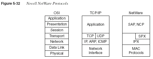
IPX routing works just like routing, as described in the section “Routing” in Chapter 3. The
logic from the routing algorithm in Chapter 3 is shown here in Figure 5-33 for reference, with
changes made to reflect IPX terminology.
Table 5-30
IPX Addressing DetailsFeature Description
Size of a group IPX addresses use a 48-bit node part of the address, giving
2
48 possible addresses per network (minus a few reservedvalues), which should be big enough.
Unique addresses IPX calls for the LAN MAC address to be used as the node
part of the IPX address. This allows for easy assignment and
little chance of duplication. Ensuring that no duplicates of
the network numbers are made is the biggest concern
because the network numbers are configured.
Grouping The grouping concept is identical to IP, with all interfaces
attached to the same medium using the same network
number. There is no equivalent of IP subnetting.
Dynamic address assignment Client IPX addresses are dynamically assigned as part of the
protocol specifications. Servers and routers are configured
with the network number(s) on their physical interfaces.
Servers can choose to automatically generate an internal
network number at installation time.
298
Chapter 5: Network Protocols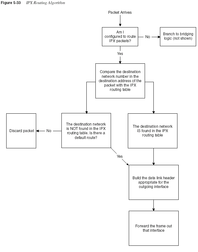
IPX Addressing and Routing
299Internal Networks and Encapsulation Types
Cisco requires that CCNAs understand encapsulation, particularly with IPX. It is always
Cisco’s desire that the professional certifications prove that the candidate knows how to make
networks that work rather than to certify individuals who are willing to memorize just for the
sake of passing the test. However, IPX encapsulation is one area in which memorization is
important once the base concepts are understood. Table 5-32, later in this section, lists several
terms you should remember.
Encapsulation is best understood in the context of two additional and important concepts
related to routing, as seen using Figure 5-34. NetWare servers use internal network numbers.
Also, clients, servers, and routers all must be configured to use the correct encapsulation.
Routing will also be reviewed using the same figure.
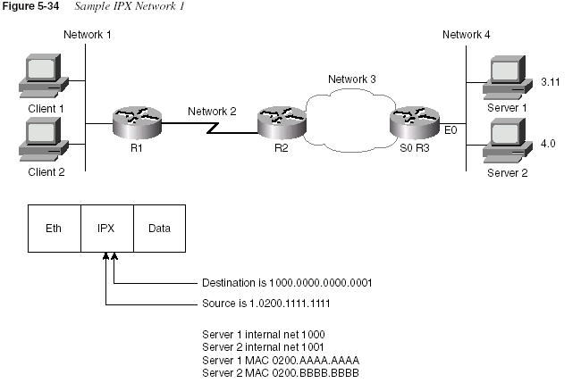
Client 1 has already logged in to Server 1 and is busily sending packets. Because NetWare
servers use an internal network number, the destination of packets from Client 1 to Server 1 is
1000.0000.0000.0001. The source address of these packets is Client 1’s IPX address
300
Chapter 5: Network Protocols(1.0200.1111.1111, in this case). Of course, the routers need network 1000 in their IPX routing
tables. For example, Table 5-31 shows the contents of the IPX routing table of R3:
R3 learned the routes to Network 3 and Network 4 because they are directly attached. The other
four routes were learned via a routing protocol, which can be RIP, EIGRP, or NLSP. (NLSP is
not covered on the CCNA exam.) Server 1 and Server 2 send RIP updates advertising networks
1000 and 1001, respectively. That is one reason why NetWare servers send RIP updates even if
they have only one interface, as is the case with Server 1.
So, servers’ internal network numbers must be in the routing tables of the routers because their
internal addresses are used as the destination address of packets.
Encapsulation is the term used by Cisco to describe the type of data link header built in the
routing algorithm illustrated in Figure 5-33. Encapsulation is also a source of confusion for
many people when considering IPX, particularly when Ethernet is in use. Consider the IPX
packet sent by Client 1 to Server 1 in Figure 5-34. Each successive router discards the data link
header of the incoming frame and builds a new data link header according to the type of
interface. However, Novell supports four different styles of Ethernet header that can be built at
R3. The types of encapsulating Ethernet headers are shown in Figure 5-35 and are listed in
Table 5-32. First, here’s a brief summary of encapsulation:
Data link encapsulation defines the details of data link headers and trailers created by a
router and placed around a packet, before completing the routing process by forwarding
the frame out an interface.
Table 5-31
IPX Routing Table, R3Network Outgoing Interface Next Router
1 s0 3.0200.0000.2222
2 s0 3.0200.0000.2222
3 s0 —
4 E0 —
1000 E0 4.0200.AAAA.AAAA
1001 E0 4.0200.BBBB.BBBB
IPX Addressing and Routing
301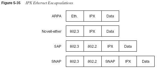
Table 5-32
IPX Ethernet EncapsulationsNovell’s Name Cisco IOS’s Name
Hints for Remembering the Names and
Meanings
Ethernet_II ARPA One way to help correlate the two names is to
remember that ARPA was the original agency that
created TCP/IP and that Ethernet_II is the older
version of Ethernet; remember that the “old” names
go together.
Ethernet_802.3 Novell-ether Novell’s name refers to the final header before the
IPX header, in this case. There are no suggestions
on easier ways to recall the IOS name Novell-ether.
This setting is Novell’s default on NetWare 3.11
and prior releases.
Ethernet_802.2 SAP Novell’s name refers to the final header before the
IPX header, in this case. Novell’s name refers to the
committee and complete header that defines the
SAP field; Cisco’s name refers to the SAP part of
the 802.2 header. (The SAP field denotes that an
IPX packet follows the 802.2 header.) This setting
is Novell’s default on NetWare 3.12 and later
releases.
Ethernet_SNAP SNAP Novell’s name refers to the final header before the
IPX header, in this case. Cisco’s name refers to this
same header.
302
Chapter 5: Network ProtocolsThe key for remembering the Novell encapsulation names is that each name refers to the header
that directly precedes the IPX packet. This can help you recall header formats as well.
Remembering the names in the order in this book can also help because the size of the headers
increases with the third and fourth options, as compared with the first two options (see Figure
5-35).
The same encapsulation issue exists on Token Ring and FDDI interfaces. Table 5-33 outlines
the options.
One or more encapsulations are needed per Ethernet interface. If all NetWare clients/servers on
the Ethernet use the same encapsulation, just that single encapsulation is needed. However, if
more than one encapsulation is used, then multiple encapsulations are needed on the router. To
configure multiple encapsulations in the IOS, multiple IPX network numbers must be used on
the same Ethernet, one per encapsulation.
Two methods of configuration can be used to create two IPX networks on the same link. The
first method uses IPX secondary addresses, and the other uses subinterfaces. Both require one
IPX network number per encapsulation type per physical interface. Both methods cause the
same protocol flows to occur. The subinterface style of configuration allows the use of NLSP,
whereas secondary interface configuration does not. (Sample configurations are shown in the
next section of this chapter.)
Table 5-33
IPX Token Ring and FDDI EncapsulationsNovell’s Name Cisco IOS’s Name Description and Hints for Remembering
FDDI_Raw Novell-fddi The IPX packet follows directly after the FDDI
header. No Type field of any kind is used.
FDDI_802.2 SAP The IPX packet follows the 802.2 header. Novell’s
name refers to the committee and complete header
that defines the SAP field; Cisco’s name refers to the
SAP part of the 802.2 header.
FDDI_SNAP SNAP Novell’s name refers to the final header before the
IPX header, in this case. Cisco’s name refers to this
same header.
Token-Ring SAP The IPX packet follows the 802.2 header. Novell’s
name refers to the committee and complete header
that defines the SAP field; Cisco’s name refers to the
SAP part of the 802.2 header.
Token-Ring_SNAP SNAP Novell’s name refers to the final header before the
IPX header. Cisco’s name refers to this same header.
IPX Configuration
303Figure 5-36 illustrates the concept of IPX secondary addressing. Server 1 uses Novell-ether, and
Server 2 uses SAP encapsulation. Network 4 devices use Novell-ether, and Network 5 devices
use SAP.
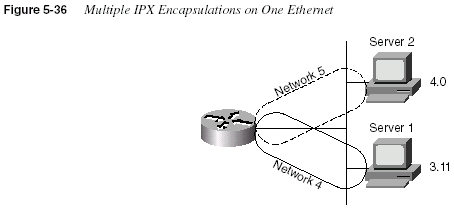
The router’s choice of encapsulation for forwarding packets is relatively straightforward. If the
route refers to a next router in Network 4, the router uses Novell-ether encapsulation. If the
route refers to a next router in Network 5, the router uses SAP encapsulation. For RIP and
SAP updates, the router sends updates on to both IPX networks, using the two different
encapsulations, respectively. This is also true if the subinterface style of supporting multiple
encapsulations is used instead of secondary addressing.
Troubleshooting can be more challenging because clients or servers using only a single
encapsulation cannot communicate directly if they are using different encapsulations. Also,
clients and servers on the same LAN that happen to use different encapsulations will require
that their packets be routed by the router so that the encapsulation is changed. Therefore, there
are many advantages to not using multiple encapsulations.
IPX Configuration
Configuration of IPX and IPX RIP on a Cisco router is relatively straightforward. Hands-on
experience is the best way to fully learn the details of configuration. In lieu of that, this section
lists commands, provides examples, and points out any tricky features. Table 5-34 and Table
5-35 summarize the more popular commands used for IPX configuration and verification. Two
configuration samples follow. The Cisco IOS documentation serves as an excellent reference
for additional IPX commands; the Cisco Press book
Installing Cisco Network Devices also isan excellent reference, particularly if you are not able to attend the instructor-led version of the
class.
304
Chapter 5: Network ProtocolsThe first sample is a basic configuration for the network in Figure 5-37. Example 5-18, Example
5-19, and Example 5-20 provide the configuration.
NOTE
The IPX samples also contain IP configuration. This is not required for correct operation ofIPX. However, to Telnet to the routers to issue commands, IP must be configured. In fact, in
almost every network with Cisco routers, IP is indeed configured. Therefore, the IPX examples
generally include IP configuration.
Table 5-34
IPX and IPX RIP Configuration CommandsCommand Configuration Mode
ipx routing
[node] Globalipx maximum-paths
paths Globalipx network
network [encapsulation type][
secondary]Interface mode
Table 5-35
IPX EXEC CommandsCommand Function
show ipx interface
Gives detailed view of IPX parameter settings,per interface
show ipx route
[network] Shows entire routing table, or one entry ifnetwork
is enteredshow ipx servers
Shows SAP tableshow ipx traffic
Shows IPX traffic statisticsdebug ipx routing
[events | activity] Gives messages describing each routing updatedebug ipx sap
[events | activity] Gives messages describing each SAP updateping
ipx-address Sends IPX packets to verify connectivityIPX Configuration
305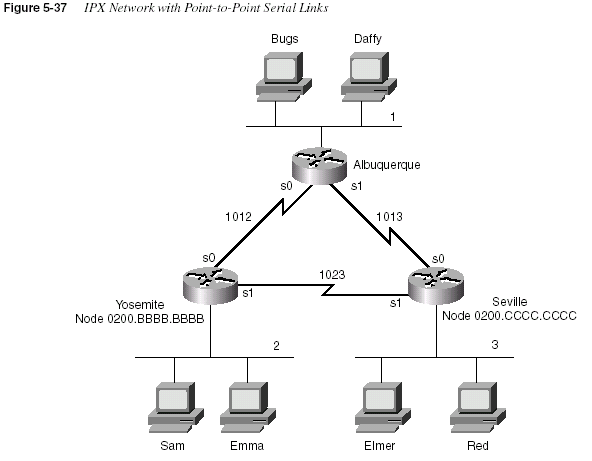
Example 5-18
Albuquerque Configuration for IPX, Sample 1ipx routing
!
interface serial0
ip address 10.1.12.1 255.255.255.0
ipx network 1012
bandwidth 56
!
interface serial1
ip address 10.1.13.1 255.255.255.0
ipx network 1013
!
interface ethernet 0
ip address 10.1.1.1 255.255.255.0
ipx network 1
306
Chapter 5: Network ProtocolsEnabling IPX routing globally as well as on each interface is all that is required to route IPX in
a Cisco router. The
ipx routing command enables IPX in this router and initializes the RIP andSAP processes. The individual
ipx network commands on each interface enable IPX routinginto and out of each interface and enable RIP and SAP on each interface, respectively.
The IPX addresses are not completely defined, however. Only the network number is
configured. The full IPX network number is created by adding the MAC address of each
interface to the configured IPX network number. For non-LAN interfaces, the MAC address of
a LAN interface is used by default. However, for easier troubleshooting, a MAC address to be
used as the node part of the IPX address on non-LAN interfaces can be configured. Notice the
Example 5-19
Yosemite Configuration for IPX, Sample 1ipx routing 0200.bbbb.bbbb
!
interface serial0
ip address 10.1.12.2 255.255.255.0
ipx network 1012
bandwidth 56
!
interface serial1
ip address 10.1.23.2 255.255.255.0
ipx network 1023
!
interface ethernet 0
ip address 10.1.2.2 255.255.255.0
ipx network 2
Example 5-20
Seville Configuration for IPX, Sample 1ipx routing 0200.cccc.cccc
!
interface serial0
ip address 10.1.13.3 255.255.255.0
ipx network 1013
!
interface serial1
ip address 10.1.23.3 255.255.255.0
ipx network 1023
!
interface ethernet 0
ip address 10.1.3.3 255.255.255.0
ipx network 3
IPX Configuration
307difference in the two commands in Example 5-21. The first is on Albuquerque, and the second
is on Seville:
Example 5-21
show ipx interface serial 0 on Albuquerque and SevilleAlbuquerque#
show ipx interface serial 0Serial0 is up, line protocol is up
IPX address is 1012.0000.0ccf.21cd [up]
Delay of this IPX network, in ticks is 6 throughput 0 link delay 0
IPXWAN processing not enabled on this interface.
IPX SAP update interval is 1 minute(s)
IPX type 20 propagation packet forwarding is disabled
Incoming access list is not set
Outgoing access list is not set
IPX helper access list is not set
SAP GNS processing enabled, delay 0 ms, output filter list is not set
SAP Input filter list is not set
SAP Output filter list is not set
SAP Router filter list is not set
Input filter list is not set
Output filter list is not set
Router filter list is not set
Netbios Input host access list is not set
Netbios Input bytes access list is not set
Netbios Output host access list is not set
Netbios Output bytes access list is not set
Updates each 60 seconds, aging multiples RIP: 3 SAP: 3
SAP interpacket delay is 55 ms, maximum size is 480 bytes
RIP interpacket delay is 55 ms, maximum size is 432 bytes
Watchdog processing is disabled, SPX spoofing is disabled, idle time 60
IPX accounting is disabled
IPX fast switching is configured (enabled)
RIP packets received 39, RIP packets sent 44
SAP packets received 27, SAP packets sent 29
Albuquerque#
Seville#
show ipx interface serial 0Serial0 is up, line protocol is up
IPX address is 1013.0200.cccc.cccc [up]
Delay of this IPX network, in ticks is 6 throughput 0 link delay 0
IPXWAN processing not enabled on this interface.
IPX SAP update interval is 1 minute(s)
IPX type 20 propagation packet forwarding is disabled
Incoming access list is not set
Outgoing access list is not set
IPX helper access list is not set
SAP GNS processing enabled, delay 0 ms, output filter list is not set
SAP Input filter list is not set
SAP Output filter list is not set
SAP Router filter list is not set
Input filter list is not set
Output filter list is not set
Router filter list is not set
continues
308
Chapter 5: Network ProtocolsThe
show ipx interface command provides a lot of information about IPX, including thecomplete IPX address. In this case, you can see that the node part of Seville’s IPX address is
easily recognizable, whereas Albuquerque’s is not. Seville’s node address is 0200.cccc.cccc
based on its
ipx routing 0200.cccc.cccc configuration command (refer to Example 5-20).However, because the node parameter was omitted from the
ipx routing command onAlbuquerque (refer to Example 5-18), the router chooses a MAC on one of the LAN interfaces
to use as the node portion of the IPX addresses on non-LAN interfaces.
NOTE
After the ipx routing command is entered, the router saves the command with the node value.In other words, even if Albuquerque’s configuration were typed as in Example 5-18, the node
number chosen from a LAN interface would be shown at the end of the
ipx routing commandwhen viewing the configuration in the future.
Several nuances are involved in how the node parts of the addresses are assigned. The first is
that if the node part of the IPX address on WAN interfaces is derived from the MAC of a LAN
interface, and if there is more than one LAN interface, then the IOS must choose one MAC
address to use. The algorithm uses the MAC address of the “first” Ethernet interface—or the
first Token Ring interface, if no Ethernet exists, or the first FDDI interface, if no Ethernet or
Token Ring exists. The lowest numbered interface number is considered to be “first.” The next
nuance is that if no LAN interfaces exist, the node parameter on the
ipx routing command mustbe configured, or IPX routing will not work on a WAN interface. The final nuance is that the
node part of IPX addresses on router LAN interfaces ignores the node parameter of the
ipxrouting
command, and uses its specific MAC address as the node part of the address.The second sample network (illustrated in Figure 5-38) uses Frame Relay with point-to-point
subinterfaces. Example 5-22, Example 5-23, Example 5-24, and Example 5-25 show the
configuration for this network.
Netbios Input host access list is not set
Netbios Input bytes access list is not set
Netbios Output host access list is not set
Netbios Output bytes access list is not set
Updates each 60 seconds, aging multiples RIP: 3 SAP: 3
SAP interpacket delay is 55 ms, maximum size is 480 bytes
RIP interpacket delay is 55 ms, maximum size is 432 bytes
Watchdog processing is disabled, SPX spoofing is disabled, idle time 60
IPX accounting is disabled
IPX fast switching is configured (enabled)
RIP packets received 51, RIP packets sent 51
SAP packets received 2, SAP packets sent 28
Seville#
Example 5-21
show ipx interface serial 0 on Albuquerque and Seville (Continued)IPX Configuration
309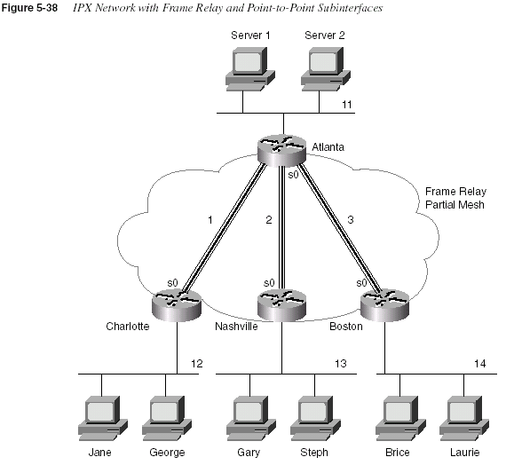
Example 5-22
Atlanta Configurationipx routing 0200.aaaa.aaaa
!
interface serial0
encapsulation frame-relay
!
interface serial 0.1 point-to-point
ip address 140.1.1.1 255.255.255.0
ipx network 1
frame-relay interface-dlci 52
!
interface serial 0.2 point-to-point
ip address 140.1.2.1 255.255.255.0
ipx network 2
continues
310
Chapter 5: Network Protocolsframe-relay interface-dlci 53
!
interface serial 0.3 point-to-point
ip address 140.1.3.1 255.255.255.0
ipx network 3
frame-relay interface-dlci 54
!
interface ethernet 0
ip address 140.1.11.1 255.255.255.0
ipx network 11
Example 5-23
Charlotte Configurationipx routing 0200.bbbb.bbbb
!
interface serial0
encapsulation frame-relay
!
interface serial 0.1 point-to-point
ip address 140.1.1.2 255.255.255.0
ipx network 1
frame-relay interface-dlci 51
!
interface ethernet 0
ip address 140.1.12.2 255.255.255.0
ipx network 12
Example 5-24
Nashville Configurationipx routing 0200.cccc.cccc
!
interface serial0
encapsulation frame-relay
!
interface serial 0.2 point-to-point
ip address 140.1.2.3 255.255.255.0
ipx network 2
frame-relay interface-dlci 51
!
interface ethernet 0
ip address 140.1.13.3 255.255.255.0
ipx network 13
Example 5-25
Boston Configurationipx routing 0200.dddd.dddd
!
interface serial0
encapsulation frame-relay
!
interface serial 0.3 point-to-point
Example 5-22
Atlanta Configuration (Continued)IPX Configuration
311The configuration is very similar to the point-to-point network of Figure 5-37. The biggest
difference is that each point-to-point subinterface is a different IPX network, as seen in Figure
5-38. Otherwise, SAP and RIP are enabled globally with the
ipx routing command; each isallowed to be broadcast on interfaces (or subinterfaces) with the
ipx network interfacesubcommand. SAP and RIP updates are sent out each subinterface—this means that Atlanta
will replicate and send three copies of the RIP update and three copies of the SAP update on its
serial0 interface, one per subinterface, every 60 seconds.
Configuration when using multiple Ethernet encapsulations is the final configuration option to
be reviewed. In Figure 5-38, assume that Gary is an old NetWare client running NetWare
version 3.11 client software and using the Ethernet_802.3 Novell encapsulation. Stephanie is
newer and uses the Ethernet_802.2 encapsulation. Two IPX networks are used on Nashville’s
Ethernet 0 interface in this case.
Gary will be in Network 13, and Stephanie will be in Network 23. Example 5-26 shows just the
Ethernet configuration for the Nashville network, with a secondary IPX network on Ethernet 0.
Example 5-26 also shows an alternative configuration using subinterfaces.
Example 5-27 shows the output of the
debug ipx sap events and debug ipx routing eventscommands. The network in Figure 5-39 was used to gather the sample output.
ip address 140.1.3.4 255.255.255.0
ipx network 3
frame-relay interface-dlci 51
!
interface ethernet 0
ip address 140.1.14.4 255.255.255.0
ipx network 14
Example 5-26
Nashville Configuration with Secondary IPX Network on Ethernet 0ipx routing 0200.cccc.cccc
!
interface ethernet 0
ipx network 13 encapsulation novell-ether
ipx network 23 encapsulation sap secondary
! Or instead of the previous 3 lines, use the following 4 lines:
interface ethernet 0.1
ipx network 13 encapsulation novell-ether
interface ethernet 0.2
ipx network 23 encapsulation sap
Example 5-25
Boston Configuration (Continued)312
Chapter 5: Network Protocols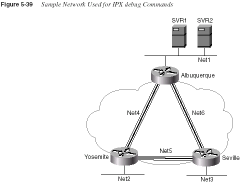
Example 5-27
IPX debug CommandsSeville#
show ipx routeCodes: C - Connected primary network, c - Connected secondary network
S - Static, F - Floating static, L - Local (internal), W - IPXWAN
R - RIP, E - EIGRP, N - NLSP, X - External, A - Aggregate
s - seconds, u - uses, U - Per-user static
9 Total IPX routes. Up to 1 parallel paths and 16 hops allowed.
No default route known.
C 3 (NOVELL-ETHER), Et0
C 5 (FRAME-RELAY), Se0.2
C 6 (FRAME-RELAY), Se0.1
R 1 [07/01] via 6.0200.aaaa.aaaa, 51s, Se0.1
R 2 [07/01] via 5.0200.bbbb.bbbb, 40s, Se0.2
R 4 [07/01] via 5.0200.bbbb.bbbb, 40s, Se0.2
R 11 [08/03] via 6.0200.aaaa.aaaa, 51s, Se0.1
R 22 [08/03] via 6.0200.aaaa.aaaa, 51s, Se0.1
R 200 [08/02] via 6.0200.aaaa.aaaa, 51s, Se0.1
Seville#
Seville#
debug ipx routing eventsIPX routing events debugging is on
01:04:03: IPXRIP: 5 FFFFFFFF not added, entry in table is static/connected/internal
01:04:12: IPXRIP: positing full update to 6.ffff.ffff.ffff via Serial0.1
(broadcast)
IPX Configuration
31301:04:14: IPXRIP: 6 FFFFFFFF not added, entry in table is static/connected/internal
01:04:14: IPXRIP: positing full update to 5.ffff.ffff.ffff via Serial0.2
(broadcast)
01:04:20: IPXRIP: positing full update to 3.ffff.ffff.ffff via Ethernet0
(broadcast)
01:05:03: IPXRIP: 5 FFFFFFFF not added, entry in table is static/connected/internal
01:05:11: IPXRIP: positing full update to 6.ffff.ffff.ffff via Serial0.1
(broadcast)
01:05:14: IPXRIP: 6 FFFFFFFF not added, entry in table is static/connected/internal
01:05:14: IPXRIP: positing full update to 5.ffff.ffff.ffff via Serial0.2
(broadcast)
01:05:20: IPXRIP: positing full update to 3.ffff.ffff.ffff via Ethernet0
(broadcast)
Seville#
debug ipx routing activityIPX routing debugging is on
Seville#
01:07:02: IPXRIP: update from 6.0200.aaaa.aaaa
01:07:02: IPXRIP: 5 FFFFFFFF not added, entry in table is static/connected/internal
01:07:02: 5 in 2 hops, delay 13
01:07:02: 200 in 2 hops, delay 8
01:07:02: 11 in 3 hops, delay 8
01:07:02: 22 in 3 hops, delay 8
01:07:02: 1 in 1 hops, delay 7
01:07:02: 2 in 2 hops, delay 13
01:07:02: 4 in 1 hops, delay 7
01:07:10: IPXRIP: positing full update to 6.ffff.ffff.ffff via Serial0.1
(broadcast)
01:07:10: IPXRIP: Update len 64 src=6.0200.cccc.cccc, dst=6.ffff.ffff.ffff(453)
01:07:10: network 3, hops 1, delay 7
01:07:10: network 4, hops 2, delay 13
01:07:10: network 2, hops 2, delay 13
01:07:10: network 5, hops 1, delay 7
01:07:13: IPXRIP: positing full update to 5.ffff.ffff.ffff via Serial0.2
(broadcast)
01:07:13: IPXRIP: Update len 80 src=5.0200.cccc.cccc, dst=5.ffff.ffff.ffff(453)
01:07:13: network 1, hops 2, delay 13
01:07:13: network 22, hops 4, delay 14
01:07:13: network 11, hops 4, delay 14
01:07:13: network 200, hops 3, delay 14
01:07:13: network 3, hops 1, delay 7
01:07:13: network 6, hops 1, delay 7
01:07:13: IPXRIP: update from 5.0200.bbbb.bbbb
01:07:13: IPXRIP: 6 FFFFFFFF not added, entry in table is static/connected/internal
01:07:13: 6 in 2 hops, delay 13
01:07:13: 22 in 4 hops, delay 14
01:07:13: 11 in 4 hops, delay 14
01:07:13: 200 in 3 hops, delay 14
01:07:13: 1 in 2 hops, delay 13
01:07:13: 2 in 1 hops, delay 7
01:07:13: 4 in 1 hops, delay 7
Example 5-27
IPX debug Commands (Continued)continues
314
Chapter 5: Network ProtocolsThe
debug ipx SAP events command lists the details of each sent and received SAP update.Notice that the number of hops to the server is shown, as is the type of service and the server
name. The source and destination of the update packets are also listed. The
debug ipx routingevents
command lists just summary information about routing updates, whereas the debug ipxrouting activity
command gives the details.Seville#
undebug allAll possible debugging has been turned off
Seville#
show ipx serversCodes: S - Static, P - Periodic, E - EIGRP, N - NLSP, H - Holddown, + = detail
U - Per-user static
4 Total IPX Servers
Table ordering is based on routing and server info
Type Name Net Address Port Route Hops Itf
P 4 SVR1 200.0000.0000.0001:0452 8/02 3 Se0.1
P 4 SVR2 200.0000.0000.0001:0452 8/02 3 Se0.1
P 7 SVR1 200.0000.0000.0001:0452 8/02 3 Se0.1
P 7 SVR2 200.0000.0000.0001:0452 8/02 3 Se0.1
Seville#
debug ipx sap activityIPX service debugging is on
Seville#
00:13:21: IPXSAP: Response (in) type 0x2 len 288 src:6.0200.aaaa.aaaa
dest:6.ffff.ffff.ffff(452)
00:13:21: type 0x4, “SVR2“, 200.0000.0000.0001(452), 3 hops
00:13:21: type 0x4, “SVR1“, 200.0000.0000.0001(452), 3 hops
00:13:21: type 0x7, “SVR2“, 200.0000.0000.0001(452), 3 hops
00:13:21: type 0x7, “SVR1“, 200.0000.0000.0001(452), 3 hops
00:13:27: IPXSAP: positing update to 6.ffff.ffff.ffff via Serial0.1 (broadcast)
(full)
00:13:27: IPXSAP: suppressing null update to 6.ffff.ffff.ffff
Seville#
Seville#
00:13:30: IPXSAP: Response (in) type 0x2 len 288 src:5.0200.bbbb.bbbb
dest:5.ffff.ffff.ffff(452)
00:13:30: type 0x7, “SVR1“, 200.0000.0000.0001(452), 4 hops
00:13:30: type 0x7, “SVR2“, 200.0000.0000.0001(452), 4 hops
00:13:30: type 0x4, “SVR1“, 200.0000.0000.0001(452), 4 hops
00:13:30: type 0x4, “SVR2“, 200.0000.0000.0001(452), 4 hops
undebug all
All possible debugging has been turned off
Seville#
Example 5-27
IPX debug Commands (Continued)Foundation Summary
315Foundation Summary
The Foundation Summary is a collection of tables and figures that provides a convenient review
of many key concepts in this chapter. For those of you already comfortable with the topics in
this chapter, this summary could help you recall a few details. For those of you who just read
this chapter, this review should help solidify some key facts. For any of you doing your final
prep before the exam, these tables and figures will hopefully be a convenient way to review the
day before the exam.
Table 5-36 lists the IP addressing terms used in this chapter.
Table 5-36
IP Addressing TerminologyTerm Definition
IP address 32-bit number, usually written in dotted decimal form, that uniquely
identifies an interface of some computer.
Host address Another term for IP address.
Network The concept of a group of hosts.
Network number A 32-bit number, usually written in dotted decimal form, that represents
a network. This number cannot be assigned as an IP address to an
interface of some computer. The host portion of the network number
has a value of all binary 0s.
Network address Another name for network number.
Broadcast address A 32-bit number, usually written in dotted decimal form, that is used to
address all hosts in the network. The host portion of the broadcast
address has a value of all binary 1s. Broadcast addresses cannot be
assigned as an IP address.
Subnet The concept of a group of hosts, which is a subdivision of a network.
Subnet number A 32-bit number, usually written in dotted decimal form, that represents
all hosts in a subnet. This number cannot be used as an IP address for
some computer’s interface.
Subnet address Another term for subnet number.
Subnetting The process of subdividing networks into smaller subnets. This is
jargon—for example, “Are you subnetting your network?”
Network mask A 32-bit number, usually written in dotted decimal form. The mask is
used by computers to calculate the network number of a given IP
address by performing a Boolean AND of the address and mask. The
mask also defines the number of host bits in an address.
continues
316
Chapter 5: Network ProtocolsTable 5-37 summarizes NAT terminology.
Mask A generic term for a mask, whether it is a default mask or a subnet
mask.
Address mask Another term for a mask.
Default Class A mask The mask used for Class A networks when no subnetting is used.
The value is 255.0.0.0.
Default Class B mask The mask used for Class B networks when no subnetting is used.
The value is 255.255.0.0.
Default Class C mask The mask used for Class C networks when no subnetting is used.
The value is 255.255.255.0.
Subnet mask A nondefault mask used when subnetting.
Network part or network
field
Term used to describe the first part of an IP address. The host part is 8,
16, or 24 bits for Class A, B, and C networks, respectively.
Host part or host field Term used to describe the last part of an IP address. The network part is
24, 16, or 8 bits for Class A, B, and C networks, respectively, when
subnetting is not used. When subnetting, the size of the host part
depends on the subnet mask chosen for that network.
Subnet part of subnet field Term used to describe the middle part of an IP address. The subnet part
is variable in size, based on how subnetting is implemented.
Table 5-37
NAT Addressing TermsTerm Meaning
Value in Figure
5-26
Inside local Address of the host in the private network. When NAT is
needed, this address is typically a private address or an
address in a network registered to another organization.
170.1.1.10
Inside global The Internet (global network) view of the inside local
address. This address is in a network registered to the
company responsible for the NAT router.
200.1.1.1
Outside global The Internet (global network) view of the address of the
host correctly attached to the Internet.
170.1.1.1
Outside local When the private company reuses a network number
registered to someone else, the outside local address
represents the outside global address in the local
(private) network. Because this address is used only in
the private organization, it can be any IP address.
192.168.1.1
Table 5-36
IP Addressing Terminology (Continued)Term Definition
Foundation Summary
317Table 5-38 contrasts typical transport layer functions as performed (or not performed) by UDP
or TCP.
Table 5-39 summarizes the ICMP unreachable codes.
Table 5-38
TCP and UDP Functional ComparisonFunction Description (TCP) Description (UDP)
Data transfer Continuous stream of ordered data Message (datagram) delivery
Multiplexing Process that allows receiving hosts to
decide the correct application for
which the data is destined, based on
port number
Process that allows receiving hosts to
decide the correct application for
which the data is destined, based on
port number
Reliable transfer Acknowledgment of data using the
sequence and acknowledgment fields
in the TCP header
Not a feature of UDP
Flow control Process used to protect buffer space
and routing devices
Not a feature of UDP
Connections Process used to initialize port numbers
and other TCP header fields
UDP is connectionless
Table 5-39
ICMP Unreachable CodesUnreachable
Code When Used
Typically Sent
By
Network
Unreachable
No match exists in a routing table for the destination of the
packet.
Router
Host Unreachable The packet can be routed to a router connected to the
destination subnet, but the host is not responding.
Router
Can’t Fragment The packet has the Don’t Fragment bit set, and a router must
fragment to forward the packet.
Router
Protocol
Unreachable
The packet is delivered to the destination host, but the
transport layer protocol is not available on that host.
Endpoint host
Port Unreachable The packet is delivered to the destination host, but the
destination port has not been opened by an application.
Endpoint host
318
Chapter 5: Network ProtocolsTable 5-40 summarizes some of the features of TFTP and FTP.
Table 5-41 lists the various codes that the Cisco IOS
ping command can supply.Figure 5-40 shows the types of encapsulating Ethernet headers that are listed and described in
Table 5-42.
Table 5-40
Comparison of FTP and TFTPFTP TFTP
Uses TCP Uses UDP
Uses robust control commands Uses simple control commands
Sends data over a separate connection than
control commands
Uses no connections, since UDP
Requires more memory and programming effort Requires less memory and programming effort
Is not supported as an application in IOS Is supported as an application in IOS
Table 5-41
Explanation of the Codes the ping Command Receives in Response to Its ICMP Echo Requestping Command Code Explanation
! ICMP Echo Reply received
. Nothing received
U ICMP unreachable (destination) received
N ICMP unreachable (network) received
P ICMP unreachable (port) received
Q ICMP Source Quench received
M ICMP “can’t fragment” message received
? Unknown packet received
Foundation Summary
319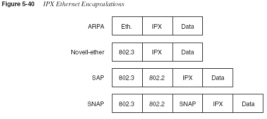
Table 5-42
IPX Ethernet EncapsulationsNovell’s Name Cisco IOS’s Name
Hints for Remembering the Names
and Meanings
Ethernet_II ARPA One way to help correlate the two names
is to remember that ARPA was the
original agency that created TCP/IP and
that Ethernet_II is the older version of
Ethernet; remember that the old names go
together.
Ethernet_802.3 Novell-ether Novell’s name refers to the final header
before the IPX header, in this case. There
are no suggestions on easier ways to
recall the IOS name Novell-ether. This
setting is Novell’s default on NetWare
3.11 and prior releases.
Ethernet_802.2 SAP Novell’s name refers to the final header
before the IPX header, in this case.
Novell’s name refers to the committee and
complete header that defines the SAP
field; Cisco’s name refers to the SAP part
of the 802.2 header. (The SAP field
denotes that an IPX packet follows the
802.2 header.) This setting is Novell’s
default on NetWare 3.12 and later
releases.
Ethernet_SNAP SNAP Novell’s name refers to the final header
before the IPX header, in this case.
Cisco’s name refers to this same header.
320
Chapter 5: Network ProtocolsFigure 5-41 shows the format of addresses when subnetting.
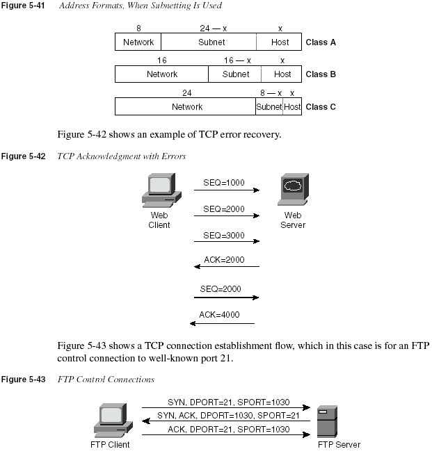
Foundation Summary
321Table 5-43 summarizes many of the most common configuration commands used for IP.
Table 5-44 summarizes the more popular commands used for IPX configuration.
Table 5-45 summarizes the
show and debug commands in this chapter and lists the examplesin the chapter in which a sample can be found.
Table 5-43
IP Configuration CommandsCommand Configuration Mode
ip address
ip-address mask [secondary] Interface modeip host
name [tcp-port-number] address1 [address2...address8] Globalip route
prefix mask {next-hop-router | output-interface} Globalip name-server
server-address1 [[server-address2]…serveraddress6]Global
ip domain-lookup
Globalip routing
Globalip netmask-format
{bitcount | decimal | hexadecimal} Interface modeip default-network
network Globalip classless
Globalip host
name [tcp-port-number] address1 [address2…address8] GlobalTable 5-44
IPX and IPX RIP Configuration CommandsCommand Configuration Mode
ipx routing
[node] Globalipx maximum-paths
paths Globalipx network
network [encapsulation type] [secondary] Interface modeTable 5-45
EXEC Command Summary for Chapter 5Command Information Supplied
show hosts
Lists all host names and corresponding IP addressesshow interface
[type number] Shows interface statistics, including IP addressshow ip interface
[type number] Gives a detailed view of IP parameter settings, per interfaceshow ip interface brief
Shows a summary of all interfaces and their IP addressesshow ip route
[subnet] Shows the entire routing table, or one entry if subnet is enteredshow ip arp
Displays the IP ARP cachecontinues
322
Chapter 5: Network Protocolsdebug ip packet
Issues log messages for each IP packetterminal ip netmask-format
{
bitcount | decimal | hexadecimal}Sets the type of display for subnet masks in
show commandsping
Sends and receives ICMP echo messages to verify connectivitytrace
Sends a series of UDP packets with increasing TTL values, toverify the current route to a host
show ipx interface
Provides a detailed view of IPX parameter settings, perinterface
show ipx route
[network] Shows the entire routing table, or one entry if network isentered
show ipx servers
Shows the SAP tableshow ipx traffic
Shows IPX traffic statisticsdebug ipx routing
[events | activity] Gives messages describing each routing updatedebug ipx sap
[events | activity] Gives messages describing each SAP updateping
ipx-address Sends IPX packets to verify connectivityTable 5-45
EXEC Command Summary for Chapter 5 (Continued)Command Information Supplied
Q&A
323Q&A
As mentioned in Chapter 1, “All About the Cisco Certified Network Associate Certification,”
the questions and scenarios in this book are more difficult than what you should experience on
the actual exam. The questions do not attempt to cover more breadth or depth than the exam;
however, they are designed to make sure that you know the answer. Rather than allowing you
to derive the answer from clues hidden inside the question itself, the questions challenge your
understanding and recall of the subject. Questions from the “Do I Know This Already?” quiz
from the beginning of the chapter are repeated here to ensure that you have mastered the
chapter’s topic areas. Hopefully, these questions will help limit the number of exam questions
on which you narrow your choices to two options and then guess.
The answers to these questions can be found in Appendix A, on page 728.
1
What do TCP, UDP, IP, and ICMP stand for? Which protocol is considered to be Layer 3equivalent when comparing TCP/IP to the OSI protocols?
2
Name the parts of an IP address.3
Define the term subnet mask. What do the bits in the mask whose values are binary 0 tellyou about the corresponding IP address(es)?
4
Given the IP address 134.141.7.11 and the mask 255.255.255.0, what is the subnetnumber?
5
Given the IP address 193.193.7.7 and the mask 255.255.255.0, what is the subnet number?6
Given the IP address 10.5.118.3 and the mask 255.255.0.0, what is the subnet number?7
Given the IP address 190.1.42.3 and the mask 255.255.255.0, what is the subnet number?8
Given the IP address 200.1.1.130 and the mask 255.255.255.224, what is the subnetnumber?
9
Given the IP address 220.8.7.100 and the mask 255.255.255.240, what is the subnetnumber?
10
Given the IP address 140.1.1.1 and the mask 255.255.255.248, what is the subnet number?11
Given the IP address 167.88.99.66 and the mask 255.255.255.192, what is the subnetnumber?
12
Given the IP address 134.141.7.11 and the mask 255.255.255.0, what is the subnetbroadcast address?
13
Given the IP address 193.193.7.7 and the mask 255.255.255.0, what is the broadcastaddress?
14
Given the IP address 10.5.118.3 and the mask 255.255.0.0, what is the broadcast address?15
Given the IP address 190.1.42.3 and the mask 255.255.255.0, what is the broadcastaddress?
324
Chapter 5: Network Protocols16
Given the IP address 200.1.1.130 and the mask 255.255.255.224, what is the broadcastaddress?
17
Given the IP address 220.8.7.100 and the mask 255.255.255.240, what is the broadcastaddress?
18
Given the IP address 140.1.1.1 and the mask 255.255.255.248, what is the broadcastaddress?
19
Given the IP address 167.88.99.66 and the mask 255.255.255.192, what is the broadcastaddress?
20
Given the IP address 134.141.7.11 and the mask 255.255.255.0, what are the assignableIP addresses in this subnet?
21
Given the IP address 193.193.7.7 and the mask 255.255.255.0, what are the assignable IPaddresses in this subnet?
22
Given the IP address 10.5.118.3 and the mask 255.255.0.0, what are the assignable IPaddresses in this subnet?
23
Given the IP address 190.1.42.3 and the mask 255.255.255.0, what are the assignable IPaddresses in this subnet?
24
Given the IP address 200.1.1.130 and the mask 255.255.255.224, what are the assignableIP addresses in this subnet?
25
Given the IP address 220.8.7.100 and the mask 255.255.255.240, what are the assignableIP addresses in this subnet?
26
Given the IP address 140.1.1.1 and the mask 255.255.255.248, what are the assignable IPaddresses in this subnet?
27
Given the IP address 167.88.99.66 and the mask 255.255.255.192, what are the assignableIP addresses in this subnet?
28
Given the IP address 134.141.7.7 and the mask 255.255.255.0, what are all the subnetnumbers if the same (static) mask is used for all subnets in this network?
29
Given the IP address 10.5.118.3 and the mask 255.255.255.0, what are all the subnetnumbers if the same (static) mask is used for all subnets in this network?
30
Given the IP address 220.8.7.100 and the mask 255.255.255.240, what are all the subnetnumbers if the same (static) mask is used for all subnets in this network?
31
Given the IP address 140.1.1.1 and the mask 255.255.255.248, what are all the subnetnumbers if the same (static) mask is used for all subnets in this network?
32
How many IP addresses could be assigned in each subnet of 134.141.0.0, assuming that amask of 255.255.255.0 is used? If the same (static) mask is used for all subnets, how many
subnets are there?
Q&A
32533
How many IP addresses could be assigned in each subnet of 10.0.0.0, assuming that amask of 255.255.255.0 is used? If the same (static) mask is used for all subnets, how many
subnets are there?
34
How many IP addresses could be assigned in each subnet of 220.8.7.0, assuming that amask of 255.255.255.240 is used? If the same (static) mask is used for all subnets, how
many subnets are there?
35
How many IP addresses could be assigned in each subnet of 140.1.0.0, assuming a maskof 255.255.255.248 is used? If the same (static) mask is used for all subnets, how many
subnets are there?
36
Create a minimal configuration enabling IP on each interface on a 2501 router (two serial,one Ethernet). The NIC assigned you network 8.0.0.0. Your boss says you need at most
200 hosts per subnet. You decide against using VLSM. Your boss also says to plan your
subnets so that you can have as many subnets as possible rather than allow for larger
subnets later. You decide to start with the lowest numerical values for the subnet number
you will use. Assume that point-to-point serial links will be attached to this router and that
RIP is the routing protocol.
37
In the previous question, what would be the IP subnet of the link attached to serial 0? Ifanother user wanted to answer the same question but did not have the enable password,
what command(s) might provide this router’s addresses and subnets?
38
Describe the question and possible responses in setup mode when a router wants to knowthe mask used on an interface. How can the router derive the correct mask from the
information supplied by the user?
39
Name the three classes of unicast IP addresses and list their default masks, respectively.How many of each type could be assigned to companies and organizations by the NIC?
40
Describe how TCP performs error recovery. What role do the routers play?41
Define the purpose of an ICMP redirect message.42
Define the purpose of the trace command. What type of messages is it sending, and whattype of ICMP messages is it receiving?
43
What does IP stand for? What does ICMP stand for? Which protocol is considered to beLayer 3 equivalent when comparing TCP/IP to the OSI protocols?
44
What causes the output from an IOS ping command to display “UUUUU?”45
Describe how to view the IP ARP cache in a Cisco router. Also describe the three keyelements of each entry.
46
How many hosts are allowed per subnet if the subnet mask used is 255.255.255.192? Howmany hosts are allowed for 255.255.255.252?
326
Chapter 5: Network Protocols47
How many subnets could be created if using static length masks in a Class B networkwhen the mask is 255.255.255.224? What about when the mask is 255.255.252.0?
48
How many bytes comprise an IPX address?49
What do IPX and SPX stand for?50
Define encapsulation in the context of Cisco routers and Novell IPX.51
Give an example of an IPX network mask used when subnetting.52
Describe the headers used for two types of Ethernet encapsulation when using IPX.53
Name the part of the NetWare protocol specifications that, like TCP, provides end-to-endguaranteed delivery of data.
54
Name the command that lists all the SAP entries in a Cisco router.55
How many different values are possible for IPX network numbers?56
Create a configuration enabling IPX on each interface, with RIP and SAP enabled on eachas well, for a 2501 (two serial, one Ethernet) router. Use networks 100, 200, and 300 for
interfaces S0, S1, and E0, respectively. Choose any node values.
57
In the previous question, what would be the IPX address of the serial 0 interface? Ifanother user wanted to know but did not have the enable password, what command(s)
might provide this IPX address?
58
What show command lists the IPX address(es) of interfaces in a Cisco router?59
How many Novell encapsulation types are valid in the IOS for Ethernet interfaces? Whatabout for FDDI and Token Ring?
60
A router is attached to an Ethernet LAN. Some clients on the LAN use Novell’sEthernet_II encapsulation, and some use Ethernet_802.3. If the only subcommand on
Ethernet0 reads
ipx network 1, which of the clients are working? (All, Ethernet_II, orEthernet_802.3?)
61
A router is attached to an Ethernet LAN. Some clients on the LAN use Novell’sEthernet_802.2 encapsulation, and some use Ethernet_SNAP. Create a configuration that
allows both types of clients to send and receive packets through this router.
62
True or false: Up to 64 IPX networks can be used on the same Ethernet by using the IPXsecondary address feature. If true, describe the largest number that is practically needed.
If false, what is the maximum number that is legal on an Ethernet?
63
In the ipx network 11 interface subcommand, does the IOS assume that 11 is binary,octal, decimal, or hexadecimal? What is the largest valid value that could be configured
instead of 11?
64
What IOS IPX encapsulation keyword implies use of an 802.2 header but no SNAPheader? On what types of interfaces is this type of encapsulation valid?
Q&A
32765
Name the two commands typically used to create a default gateway for a router.66
Assume that subnets of network 10.0.0.0 are in the IP routing table in a router but that noother network and their subnets are known, except that there is also a default route
(0.0.0.0) in the routing table. A packet destined for 192.1.1.1 arrives at the router. What
configuration command determines whether the default route will be used in this case?
67
Assume that subnets of network 10.0.0.0 are in the IP routing table in a router but thatno other network and their subnets are known, except that there is also a default route
(0.0.0.0) in the routing table. A packet destined for 10.1.1.1 arrives at the router, but
there is no known subnet of network 10 that matches this destination address. What
configuration command determines whether the default route will be used in this case?
68
What does the acronym CIDR stand for? What is the original purpose of CIDR?69
Define the term private addressing as defined in RFC 1918.70
Define the acronym NAT, and define the basics of its operation.71
Which requires more lines of source code, FTP or TFTP? Justify your answer.72
Does FTP or TFTP perform error recovery? If so, describe the basics of how they performerror recovery.
73
Describe the process used by IP routers to perform fragmentation and reassembly ofpackets.
74
How many TCP segments are exchanged to establish a TCP connection? How many arerequired to terminate a TCP connection?
75
How many Class B-style networks are reserved by RFC 1918 private addressing?328
Chapter 5: Network ProtocolsScenarios
Scenario 5-1: IP Addressing and Subnet Calculation
Assume that you just took a new job. No one trusts you yet, so they will not give you any
passwords to the router. Your mentor at your new company has left you at his desk while he goes
to a meeting. He has left a Telnet window up, logged in to one router in user mode. In other
words, you can issue only user mode commands.
Assuming that you had issued the following commands (see Example 5-28), draw the most
specific network diagram that you can. Write the subnet numbers used on each link onto the
diagram.
Example 5-28
Command Output on Router Fredfred>
show interfaceSerial0 is up, line protocol is up
Hardware is HD64570
Internet address is 199.1.1.65/27
MTU 1500 bytes, BW 1544 Kbit, DLY 20000 usec, rely 255/255, load 1/255
Encapsulation HDLC, loopback not set, keepalive set (10 sec)
Last input 00:00:07, output 00:00:10, output hang never
Last clearing of “show interface” counters never
Input queue: 0/75/0 (size/max/drops); Total output drops: 0
Queuing strategy: weighted fair
Output queue: 0/1000/0 (size/max total/drops)
Conversations 0/1/64 (active/max active/threshold)
Reserved Conversations 0/0 (allocated/max allocated)
5 minute input rate 0 bits/sec, 0 packets/sec
5 minute output rate 0 bits/sec, 0 packets/sec
27 packets input, 2452 bytes, 0 no buffer
Received 27 broadcasts, 0 runts, 0 giants, 0 throttles
0 input errors, 0 CRC, 0 frame, 0 overrun, 0 ignored, 0 abort
29 packets output, 2044 bytes, 0 underruns
0 output errors, 0 collisions, 28 interface resets
0 output buffer failures, 0 output buffers swapped out
7 carrier transitions
DCD=up DSR=up DTR=up RTS=up CTS=up
Serial1 is up, line protocol is up
Hardware is HD64570
Internet address is 199.1.1.97/27
MTU 1500 bytes, BW 1544 Kbit, DLY 20000 usec, rely 255/255, load 1/255
Encapsulation HDLC, loopback not set, keepalive set (10 sec)
Last input 00:00:01, output 00:00:01, output hang never
Last clearing of “show interface” counters never
Input queue: 0/75/0 (size/max/drops); Total output drops: 0
Queuing strategy: weighted fair
Output queue: 0/1000/0 (size/max total/drops)
Conversations 0/1/64 (active/max active/threshold)
Reserved Conversations 0/0 (allocated/max allocated)
5 minute input rate 0 bits/sec, 0 packets/sec
Scenario 5-1: IP Addressing and Subnet Calculation
3295 minute output rate 0 bits/sec, 0 packets/sec
125 packets input, 7634 bytes, 0 no buffer
Received 124 broadcasts, 0 runts, 0 giants, 0 throttles
0 input errors, 0 CRC, 0 frame, 0 overrun, 0 ignored, 0 abort
161 packets output, 9575 bytes, 0 underruns
0 output errors, 0 collisions, 1 interface resets
0 output buffer failures, 0 output buffers swapped out
4 carrier transitions
DCD=up DSR=up DTR=up RTS=up CTS=up
Ethernet0 is up, line protocol is up
Hardware is MCI Ethernet, address is 0000.0c55.AB44 (bia 0000.0c55.AB44)
Internet address is 199.1.1.33/27
MTU 1500 bytes, BW 10000 Kbit, DLY 1000 usec, rely 255/255, load 1/255
Encapsulation ARPA, loopback not set, keepalive set (10 sec)
ARP type: ARPA, PROBE, ARP Timeout 4:00:00 Last input 0:00:00, output
0:00:00, output hang never
Output queue 0/40, 0 drops; input queue 0/75, 0 drops
Five minute input rate 4000 bits/sec, 4 packets/sec
Five minute output rate 6000 bits/sec, 6 packets/sec
22197 packets input, 309992 bytes, 0 no buffer
Received 2343 broadcasts, 0 runts, 0 giants
0 input errors, 0 CRC, 0 frame, 0 overrun, 0 ignored, 0 abort
4456 packets output, 145765 bytes, 0 underruns
3 output errors, 10 collisions, 2 interface resets, 0 restarts
fred>
show ip routeCodes: C - connected, S - static, I - IGRP, R - RIP, M - mobile, B - BGP
D - EIGRP, EX - EIGRP external, O - OSPF, IA - OSPF inter area
N1 - OSPF NSSA external type 1, N2 - OSPF NSSA external type 2
E1 - OSPF external type 1, E2 - OSPF external type 2, E - EGP
i - IS-IS, L1 - IS-IS level-1, L2 - IS-IS level-2, * - candidate default
U - per-user static route, o - ODR
Gateway of last resort is not set
199.1.1.0/27 is subnetted, 6 subnets
R 199.1.1.192 [120/1] via 199.1.1.98, 00:00:01, Serial1
R 199.1.1.128 [120/1] via 199.1.1.98, 00:00:01, Serial1
[120/1] via 199.1.1.66, 00:00:20, Serial0
R 199.1.1.160 [120/1] via 199.1.1.66, 00:00:20, Serial0
C 199.1.1.64 is directly connected, Serial0
C 199.1.1.96 is directly connected, Serial1
C 199.1.1.32 is directly connected, Ethernet0
fred>
show ip protocolRouting Protocol is “rip“
Sending updates every 30 seconds, next due in 23 seconds
Invalid after 180 seconds, hold down 180, flushed after 240
Outgoing update filter list for all interfaces is not set
Incoming update filter list for all interfaces is not set
Example 5-28
Command Output on Router Fred (Continued)continues
330
Chapter 5: Network ProtocolsScenario 5-2: IP Subnet Design with a Class B Network
Your job is to plan a new network. The topology required includes three sites, one Ethernet at
each site, and point-to-point serial links for connectivity, as shown in Figure 5-44. The network
may grow to need at most 100 subnets, with 200 hosts per subnet maximum. Use network
172.16.0.0. Use Table 5-46 to record your choices, or use a separate piece of paper.
Redistributing: rip
Default version control: send version 1, receive any version
Interface Send Recv Key-chain
Serial0 1 1 2
Serial1 1 1 2
Ethernet0 1 1 2
Routing for Networks:
199.1.1.0
Routing Information Sources:
Gateway Distance Last Update
199.1.1.66 120 00:00:04
199.1.1.98 120 00:00:14
Distance: (default is 120)
fred>
show cdp neighbor detail-------------------------
Device ID: dino
Entry address(es):
IP address: 199.1.1.66
Platform: Cisco 2500, Capabilities: Router
Interface: Serial0, Port ID (outgoing port): Serial0
Holdtime : 148 sec
Version :
Cisco Internetwork Operating System Software
IOS (tm) 2500 Software (C2500-AINR-L), Version 11.2(11), RELEASE SOFTWARE (fc1)
Copyright 1986-1997 by Cisco Systems, Inc.
Compiled Mon 29-Dec-97 18:47 by ckralik
-------------------------
Device ID: Barney
Entry address(es):
IP address: 199.1.1.98
Platform: Cisco 2500, Capabilities: Router
Interface: Serial1, Port ID (outgoing port): Serial0
Holdtime : 155 sec
Version :
Cisco Internetwork Operating System Software
IOS (tm) 2500 Software (C2500-AINR-L), Version 11.2(11), RELEASE SOFTWARE (fc1)
Copyright 1986-1997 by Cisco Systems, Inc.
Compiled Mon 29-Dec-97 18:47 by ckralik
Example 5-28
Command Output on Router Fred (Continued)Scenario 5-3: IP Subnet Design with a Class C Network
331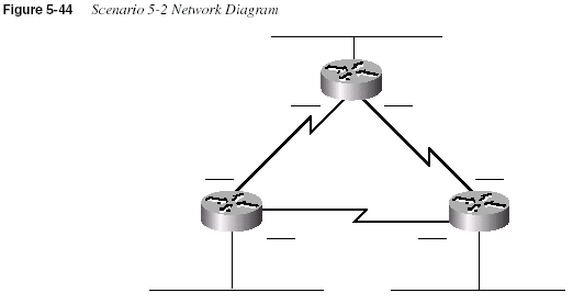
Given the information in Figure 5-44 and Table 5-46, perform the following activities:
1
Determine all subnet masks that meet the criteria in the introduction to this scenario.2
Choose a mask and pick enough subnets to use for the original topology (refer toFigure 5-44).
3
Create IP-related configuration commands for each router.Scenario 5-3: IP Subnet Design with a Class C Network
Your job is to plan yet another network. The topology required includes four sites, one Ethernet
at each site, and partially meshed Frame Relay for connectivity, as shown in Figure 5-45. The
number of subnets will never grow. Choose a mask that will maximize the number of hosts per
Table 5-46
Scenario 5-2 Planning ChartLocation of Subnet
Geographically Subnet Mask Subnet Number
Router’s IP
Address
Ethernet off Router A
Ethernet off Router B
Ethernet off Router C
Serial between A and B
Serial between A and C
Serial between B and C
332
Chapter 5: Network Protocolssubnet. Use network 200.1.1.0. Use Table 5-47 to record your choices, or use a separate piece
of paper.
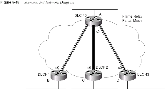
Given the network setup in Figure 5-45, perform the following activities:
1
Choose the best subnet mask that meets the criteria.2
Use Table 5-47 to plan which subnet numbers will be used.3
Create IP-related configuration commands for each router. Use the DLCIs fromFigure 5-45.
Table 5-47
Scenario 5-3 Planning ChartLocation of Subnet Subnet Mask Subnet Number
Router’s IP
Address
Ethernet off Router A
Ethernet off Router B
Ethernet off Router C
Ethernet off Router D
VC between A and B
VC between A and C
VC between A and D
Scenario 5-4: IPX Examination
333Scenario 5-4: IPX Examination
Given the network in Figure 5-46 and the command output in Example 5-29, Example 5-30,
and Example 5-31, answer the questions and perform the tasks listed after Example 5-31.
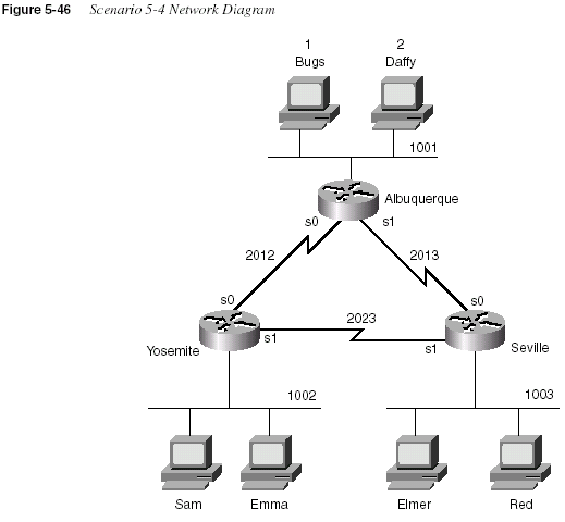
Example 5-29
Albuquerque Command Output, Scenario 5-4Albuquerque#
show ipx interface briefInterface IPX Network Encapsulation Status IPX State
Serial0 2012 HDLC up [up]
Serial1 2013 HDLC up [up]
Ethernet0 1001 SAP up [up]
Albuquerque#
show cdp neighbor detail-------------------------
Device ID: Yosemite
Entry address(es):
IP address: 10.1.12.2
Novell address: 2012.0200.2222.2222
continues
334
Chapter 5: Network ProtocolsPlatform: cisco 2500, Capabilities: Router
Interface: Serial0, Port ID (outgoing port): Serial0
Holdtime : 167 sec
Version :
Cisco Internetwork Operating System Software
IOS (tm) 2500 Software (C2500-AINR-L), Version 11.2(11), RELEASE SOFTWARE (fc1)
Copyright 1986-1997 by Cisco Systems, Inc.
Compiled Mon 29-Dec-97 18:47 by ckralik
-------------------------
Device ID: Seville
Entry address(es):
IP address: 10.1.13.3
Novell address: 2013.0200.3333.3333
Platform: cisco 2500, Capabilities: Router
Interface: Serial1, Port ID (outgoing port): Serial0
Holdtime : 164 sec
Version :
Cisco Internetwork Operating System Software
IOS (tm) 2500 Software (C2500-AINR-L), Version 11.2(11), RELEASE SOFTWARE (fc1)
Copyright 1986-1997 by Cisco Systems, Inc.
Compiled Mon 29-Dec-97 18:47 by ckralik
Example 5-30
Yosemite Command Output, Scenario 5-4Yosemite#
show ipx routeCodes: C - Connected primary network, c - Connected secondary network
S - Static, F - Floating static, L - Local (internal), W - IPXWAN
R - RIP, E - EIGRP, N - NLSP, X - External, A - Aggregate
s - seconds, u - uses
8 Total IPX routes. Up to 1 parallel paths and 16 hops allowed.
No default route known.
C 1002 (SAP), E0
C 2012 (HDLC), Se0
C 2023 (HDLC), Se1
R 1 [08/03] via 2012.0200.1111.1111, 32s, Se0
R 2 [08/03] via 2012.0200.1111.1111, 33s, Se0
R 1001 [07/01] via 2012.0200.1111.1111, 33s, Se0
R 1003 [07/01] via 2023.0200.3333.3333, 32s, Se1
R 2013 [07/01] via 2012.0200.1111.1111, 33s, Se0
Yosemite#
show ipx trafficSystem Traffic for 0.0000.0000.0001 System-Name: Yosemite
Rcvd: 169 total, 0 format errors, 0 checksum errors, 0 bad hop count,
8 packets pitched, 161 local destination, 0 multicast
Bcast: 160 received, 242 sent
Sent: 243 generated, 0 forwarded
Example 5-29
Albuquerque Command Output, Scenario 5-4 (Continued)Scenario 5-4: IPX Examination
3350 encapsulation failed, 0 no route
SAP: 2 SAP requests, 0 SAP replies, 2 servers
0 SAP Nearest Name requests, 0 replies
0 SAP General Name requests, 0 replies
60 SAP advertisements received, 57 sent
6 SAP flash updates sent, 0 SAP format errors
RIP: 1 RIP requests, 0 RIP replies, 9 routes
98 RIP advertisements received, 120 sent
45 RIP flash updates sent, 0 RIP format errors
Echo: Rcvd 0 requests, 0 replies
Sent 0 requests, 0 replies
0 unknown: 0 no socket, 0 filtered, 0 no helper
0 SAPs throttled, freed NDB len 0
Watchdog:
0 packets received, 0 replies spoofed
Queue lengths:
IPX input: 0, SAP 0, RIP 0, GNS 0
SAP throttling length: 0/(no limit), 0 nets pending lost route reply
Delayed process creation: 0
EIGRP: Total received 0, sent 0
Updates received 0, sent 0
Queries received 0, sent 0
Replies received 0, sent 0
SAPs received 0, sent 0
NLSP: Level-1 Hellos received 0, sent 0
PTP Hello received 0, sent 0
Level-1 LSPs received 0, sent 0
LSP Retransmissions: 0
LSP checksum errors received: 0
LSP HT=0 checksum errors received: 0
Level-1 CSNPs received 0, sent 0
Level-1 PSNPs received 0, sent 0
Level-1 DR Elections: 0
Level-1 SPF Calculations: 0
Level-1 Partial Route Calculations: 0
Example 5-31
Seville Command Output, Scenario 5-4Seville#
show ipx interfaceSerial0 is up, line protocol is up
IPX address is 2013.0200.3333.3333 [up]
Delay of this IPX network, in ticks is 6 throughput 0 link delay 0
IPXWAN processing not enabled on this interface.
IPX SAP update interval is 1 minute(s)
IPX type 20 propagation packet forwarding is disabled
Incoming access list is not set
Outgoing access list is not set
IPX helper access list is not set
SAP GNS processing enabled, delay 0 ms, output filter list is not set
SAP Input filter list is not set
SAP Output filter list is not set
Example 5-30
Yosemite Command Output, Scenario 5-4 (Continued)continues
336
Chapter 5: Network ProtocolsSAP Router filter list is not set
Input filter list is not set
Output filter list is not set
Router filter list is not set
Netbios Input host access list is not set
Netbios Input bytes access list is not set
Netbios Output host access list is not set
Netbios Output bytes access list is not set
Updates each 60 seconds, aging multiples RIP: 3 SAP: 3
SAP interpacket delay is 55 ms, maximum size is 480 bytes
RIP interpacket delay is 55 ms, maximum size is 432 bytes
Watchdog processing is disabled, SPX spoofing is disabled, idle time 60
IPX accounting is disabled
IPX fast switching is configured (enabled)
RIP packets received 53, RIP packets sent 55
SAP packets received 14, SAP packets sent 25
Serial1 is up, line protocol is up
IPX address is 2023.0200.3333.3333 [up]
Delay of this IPX network, in ticks is 6 throughput 0 link delay 0
IPXWAN processing not enabled on this interface.
IPX SAP update interval is 1 minute(s)
IPX type 20 propagation packet forwarding is disabled
Incoming access list is not set
Outgoing access list is not set
IPX helper access list is not set
SAP GNS processing enabled, delay 0 ms, output filter list is not set
SAP Input filter list is not set
SAP Output filter list is not set
SAP Router filter list is not set
Input filter list is not set
Output filter list is not set
Router filter list is not set
Netbios Input host access list is not set
Netbios Input bytes access list is not set
Netbios Output host access list is not set
Netbios Output bytes access list is not set
Updates each 60 seconds, aging multiples RIP: 3 SAP: 3
SAP interpacket delay is 55 ms, maximum size is 480 bytes
RIP interpacket delay is 55 ms, maximum size is 432 bytes
Watchdog processing is disabled, SPX spoofing is disabled, idle time 60
IPX accounting is disabled
IPX fast switching is configured (enabled)
RIP packets received 53, RIP packets sent 62
SAP packets received 13, SAP packets sent 37
Ethernet0 is up, line protocol is up
IPX address is 1003. 0000.0cac.ab41, SAP [up]
Delay of this IPX network, in ticks is 1 throughput 0 link delay 0
IPXWAN processing not enabled on this interface.
IPX SAP update interval is 1 minute(s)
IPX type 20 propagation packet forwarding is disabled
Incoming access list is not set
Outgoing access list is not set
IPX helper access list is not set
Example 5-31
Seville Command Output, Scenario 5-4 (Continued)Scenario 5-4: IPX Examination
337Assuming the details established in Figure 5-46 and the command output in Example 5-29,
Example 5-30, and Example 5-31 for Scenario 5-4, complete or answer the following:
1
Complete Table 5-48 with all IPX network numbers. List the command(s) you use to findthese network numbers.
2
Complete as much of Table 5-49 as possible.SAP GNS processing enabled, delay 0 ms, output filter list is not set
SAP Input filter list is not set
SAP Output filter list is not set
SAP Router filter list is not set
Input filter list is not set
Output filter list is not set
Router filter list is not set
Netbios Input host access list is not set
Netbios Input bytes access list is not set
Netbios Output host access list is not set
Netbios Output bytes access list is not set
Updates each 60 seconds, aging multiples RIP: 3 SAP: 3
SAP interpacket delay is 55 ms, maximum size is 480 bytes
RIP interpacket delay is 55 ms, maximum size is 432 bytes
IPX accounting is disabled
IPX fast switching is configured (enabled)
RIP packets received 20, RIP packets sent 62
SAP packets received 18, SAP packets sent 15
Seville#
show ipx serversCodes: S - Static, P - Periodic, E - EIGRP, N - NLSP, H - Holddown, + = detail
2 Total IPX Servers
Table ordering is based on routing and server info
Type Name Net Address Port Route Hops Itf
P 4 Bugs 1.0000.0000.0001:0451 8/03 3 Se0
P 4 Daffy 2.0000.0000.0001:0451 8/03 3 Se0
Table 5-48
IPX Networks in Scenario 5-4IPX Network
Location (Such as
“Between Albuquerque
and Seville”)
Command Used to Find
This Information
Example 5-31
Seville Command Output, Scenario 5-4 (Continued)continues
338
Chapter 5: Network ProtocolsTable 5-49
IPX Addresses on Routers in Scenario 5-4Router Interface IPX Network IPX Node
Albuquerque E0
S0
S1
Yosemite E0
S0
S1
Seville E0
S0
S1
Table 5-48
IPX Networks in Scenario 5-4 (Continued)IPX Network
Location (Such as
“Between Albuquerque
and Seville”)
Command Used to Find
This Information
Scenario 5-5: IPX Configuration
339Scenario 5-5: IPX Configuration
Assume the network setup in Figure 5-47.
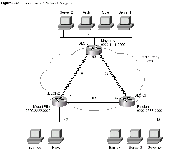
Assuming the details established in Figure 5-47 for Scenario 5-5, complete or answer the
following:
1
Configure IPX on all three routers. Use the network numbers listed in the figure. (Do notbother with IP.) Use point-to-point subinterfaces, and use the IPX node addresses shown
in the diagram on the serial interfaces.
2
You later find out that Beatrice is using NetWare’s Ethernet_II encapsulation, Floyd isusing Ethernet_802.3, Barney is using Ethernet_802.2, and Governor is using
Ethernet_SNAP. Configure the changes necessary to support each client.
340
Chapter 5: Network ProtocolsScenario Answers
Answers to Scenario 5-1: IP Addressing and Subnet
Calculation
Assuming that you had issued the commands in Example 5-28, the most specific network
diagram would look like Figure 5-48.
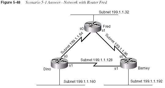
The clues that you should have found in the
show commands are as follows:•
The types and IP addresses of the interfaces on Fred were in the show interface and showip interface brief
command output.•
The subnets could be learned from the show ip route command or derived from the IPaddresses and masks shown in the
show interface command output.•
The neighboring router’s IP addresses could be learned from the show ip protocolcommand.
•
The neighboring routers’ IP addresses and host names could be learned from the showcdp neighbor detail
command.•
The metric for subnet 199.1.1.128/27 in RIP updates implies that both neighbors have anequal-cost route to the same subnet. Because two separate but duplicate networks would
be a bad design, you can assume that the neighboring routers are attached to the same
medium.
Answers to Scenario 5-2: IP Subnet Design with a Class B Network
341•
If completely bored, the telnet 199.1.1.x command could have been issued for all IPaddresses in subnets not directly connected to Fred, hoping to get a router login prompt.
That would identify the IP addresses of other router interfaces.
There is no way to know what physical media are beyond the neighboring routers. However,
because CDP claims that both routers are 2500 series routers, the possible interfaces on these
neighboring routers are limited. Figure 5-48 shows the other subnets as Ethernet segments.
Similarly, the figure shows the two neighboring routers attached to the same medium, which is
shown as a serial link in Figure 5-48.
Answers to Scenario 5-2: IP Subnet Design with a Class
B Network
Figure 5-49 shows one correct answer for the network skeleton presented in Figure 5-44.
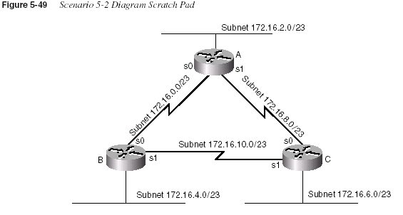
Answers to Task 1 for Scenario 5-2
Given the details in Figure 5-44 and Table 5-46 for Scenario 5-2, the subnet mask criteria are
as follows:
•
200 hosts in a subnet, maximum•
100 subnets, maximum•
Static size masks used all over this network342
Chapter 5: Network ProtocolsSo, the mask must have at least 8 host bits because 2
7 × 128 is not enough and 28 × 256 is morethan enough for numbering 200 hosts in a subnet. The mask must have at least 7 subnet bits,
likewise, because 2
7 is the smallest power of 2 that is larger than 100, which is the requirednumber of subnets. The first 16 bits in the mask must be binary 1 because a Class B network
(172.16.0.0) is used. Figure 5-50 diagrams the possibilities.

The only bit position in which a decision can be made is the 24th bit, shown with an x in Figure
5-50. That leaves two mask possibilities: 255.255.254.0 and 255.255.255.0. This sample shows
the 255.255.254.0 mask because 255.255.255.0 is more intuitive.
Answers to Task 2 for Scenario 5-2
To choose a mask and pick enough subnets to use for the original topology illustrated in Figure
5-44, a review of the longer binary algorithm and shortcut algorithm for deriving subnet
numbers is required. To review, subnet numbers have the network number binary value in the
network portion of the subnet numbers and have all binary 0s in the host bits. The bits that vary
from subnet to subnet are the subnet bits—in other words, you are numbering different subnets
in the subnet field.
Valid subnets with mask 255.255.254.0 are as follows:
172.16.0.0 (zero subnet)
172.16.2.0
172.16.4.0
172.16.6.0
.
.
.
172.16.252.0
172.16.254.0 (broadcast subnet)
Answers to Scenario 5-2: IP Subnet Design with a Class B Network
343The first six subnets, including the zero subnet, were chosen for this example, as listed in
Table 5-50.
Answers to Task 3 for Scenario 5-2
Given the details in Figure 5-44 and Table 5-46 for Scenario 5-2, the configurations in Example
5-32, Example 5-33, and Example 5-34 satisfy the exercise of creating IP-related configuration
commands for each router. These examples include only the IP-related commands.
Table 5-50
Scenario 5-2 Subnets and AddressesLocation of Subnet
Geographically Subnet Mask Subnet Number Router’s IP Address
Ethernet off Router A 255.255.254.0 172.16.2.0 172.16.2.1
Ethernet off Router B 255.255.254.0 172.16.4.0 172.16.4.2
Ethernet off Router C 255.255.254.0 172.16.6.0 172.16.6.3
Serial between A and B 255.255.254.0 172.16.0.0 172.16.0.1 (A) and .2
(B)
Serial between A and C 255.255.254.0 172.16.8.0 172.16.8.1 (A) and .3
Serial between B and C 255.255.254.0 172.16.10.0 172.16.10.2 (B) and .3
Example 5-32
Router A Configuration, Scenario 5-2ip subnet-zero
no ip domain-lookup
!
interface serial0
ip address 172.16.0.1 255.255.254.0
interface serial 1
ip address 172.16.8.1 255.255.254.0
interface ethernet 0
ip address 172.16.2.1 255.255.254.0
!
router igrp 6
network 172.16.0.0
Example 5-33
Router B Configuration, Scenario 5-2ip subnet-zero
no ip domain-lookup
!
interface serial0
ip address 172.16.0.2 255.255.254.0
interface serial 1
ip address 172.16.10.2 255.255.254.0
interface ethernet 0
ip address 172.16.4.2 255.255.254.0
continues
344
Chapter 5: Network ProtocolsAnswers to Scenario 5-3: IP Subnet Design with a Class
C Network
Planning the network in this scenario requires a topology that includes four sites, one Ethernet
at each site, and partially meshed Frame Relay for connectivity, as shown previously in Figure
5-45. The number of subnets will never grow. You must choose a mask that will maximize the
number of hosts per subnet, and you must use network 200.1.1.0.
Answers to Task 1 for Scenario 5-3
Given the design criteria and the network setup illustrated in Figure 5-45, this scenario requires
tricky subnet masks because a Class C network is used and because subnetting is needed. Using
Frame Relay subinterfaces, there will be a need for seven different subnets—one for each
Ethernet and one for each Frame Relay VC.
If 3 subnet bits are used, eight mathematical possibilities exist for subnet numbers. However,
one is the zero subnet and the other is the broadcast subnet. In this case, use of one or the other
is desired because the design called for maximizing the number of hosts per subnet. Deciding
against use of the zero and broadcast subnets then would require 4 subnet bits, leaving only 4
host bits, implying 14 hosts per subnet. So, 3 subnet bits and 5 host bits will be used in this
solution (mask of 255.255.255.224). Figure 5-51 summarizes the subnets on the network
diagram.
!
router igrp 6
network 172.16.0.0
Example 5-34
Router C Configuration, Scenario 5-2ip subnet-zero
no ip domain-lookup
!
interface serial0
ip address 172.16.8.3 255.255.254.0
interface serial 1
ip address 172.16.10.3 255.255.254.0
interface ethernet 0
ip address 172.16.6.3 255.255.254.0
!
router igrp 6
network 172.16.0.0
Example 5-33
Router B Configuration, Scenario 5-2 (Continued)Answers to Scenario 5-3: IP Subnet Design with a Class C Network
345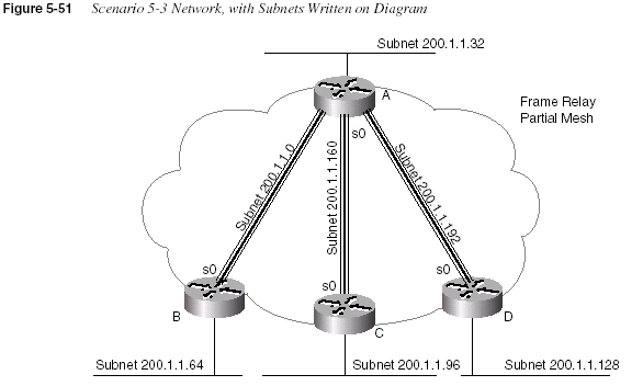
Answers to Task 2 for Scenario 5-3
Given the design criteria and the network setup illustrated in Figure 5-45 for Scenario 5-3, Table
5-51 shows the choices of subnets and addresses in this example. Only one subnet, 200.1.1.224,
which is the broadcast subnet, is not used. Of course, you could have chosen a different
set of subnets and used them on different links, but the mask you used should have been
255.255.255.224, based on the criteria to maximize the number of hosts per subnet.
Table 5-51
Scenario 5-3 Addresses and SubnetsLocation of Subnet Subnet Mask Subnet Number Router’s IP Address
Ethernet off Router A 255.255.255.224 200.1.1.32 200.1.1.33
Ethernet off Router B 255.255.255.224 200.1.1.64 200.1.1.65
Ethernet off Router C 255.255.255.224 200.1.1.96 200.1.1.97
Ethernet off Router D 255.255.255.224 200.1.1.128 200.1.1.129
VC between A and B 255.255.255.224 200.1.1.0 200.1.1.1 (A) and .2
(B)
VC between A and C 255.255.255.224 200.1.1.160 200.1.1.161 (A) and
.162 (B)
VC between A and D 255.255.255.224 200.1.1.192 200.1.1.193 (A) and
.194 (B)
346
Chapter 5: Network ProtocolsAnswers to Task 3 for Scenario 5-3
Using the DLCIs from Figure 5-45, you can find the IP-related configuration commands for
each router in Example 5-35, Example 5-36, Example 5-37, and Example 5-38.
Example 5-35
Router A Configuration, Scenario 5-3ip subnet-zero
no ip domain-lookup
!
interface serial0
encapsulation frame-relay
interface serial 0.1
ip address 200.1.1.1 255.255.255.224
frame-relay interface-dlci 41
!
interface serial 0.2
ip address 200.1.1.161 255.255.255.224
interface-dlci 42
!
interface serial 0.3
ip address 200.1.1.193 255.255.255.224
frame-relay interface-dlci 43
!
interface ethernet 0
ip address 200.1.1.33 255.255.255.224
!
router igrp 6
network 200.1.1.0
Example 5-36
Router B Configuration, Scenario 5-3ip subnet-zero
no ip domain-lookup
!
interface serial0
encapsulation frame-relay
interface serial 0.1
ip address 200.1.1.2 255.255.255.224
frame-relay interface-dlci 40
!
interface ethernet 0
ip address 200.1.1.65 255.255.255.224
!
router igrp 6
network 200.1.1.0
Answers to Scenario 5-4: IPX Examination
347Answers to Scenario 5-4: IPX Examination
Assuming the details established in Figure 5-46 and the command output in Example 5-29,
Example 5-30, and Example 5-31 for Scenario 5-4, the
show ipx interface brief command andshow ipx route
command are the best methods for learning the network numbers in Table5-52 (Task 1, for this scenario).
Example 5-37
Router C Configuration, Scenario 5-3ip subnet-zero
no ip domain-lookup
!
interface serial0
encapsulation frame-relay
frame-relay interface serial 0.1
ip address 200.1.1.162 255.255.255.224
frame-relay interface-dlci 40
!
interface ethernet 0
ip address 200.1.1.97 255.255.255.224
!
router igrp 6
network 200.1.1.0
Example 5-38
Router D Configuration, Scenario 5-3ip subnet-zero
no ip domain-lookup
!
interface serial0
encapsulation frame-relay
interface serial 0.1
ip address 200.1.1.194 255.255.255.224
frame-relay interface-dlci 40
!
interface ethernet 0
ip address 200.1.1.129 255.255.255.224
!
router igrp 6
network 200.1.1.0
Table 5-52
IPX Networks in Scenario 5-4—Completed ChartIPX Network
Location (Such as “Between
Albuquerque and Seville”)
Command Used to Find This
Information
1001 Albuquerque Ethernet0
show ipx interface brief onAlbuquerque
show ipx route
on Yosemitecontinues
348
Chapter 5: Network ProtocolsAssuming the details established in Figure 5-46 and the command output in Example 5-29,
Example 5-30, and Example 5-31 for Scenario 5-4, the network numbers are obtained from
several sources, as seen in Table 5-52. The additional requirement for Task 2 is to find the node
part of the IPX addresses on each interface. The easy way to learn this information is through
the
show ipx interface command. Of course, only one such command was provided inExample 5-29, Example 5-30, and Example 5-31. The answers that could be found in the
examples are listed in Table 5-53.
1002 Yosemite Ethernet0
show ipx route on Yosemite1003 Seville Ethernet0
show cdp neighbor detail onAlbuquerque
show ipx interface
on Seville2012 Albuquerque–Yosemite
show cdp neighbor detail onAlbuquerque
show ipx route
on Yosemiteshow ipx interface brief
onAlbuquerque
2013 Albuquerque–Seville
show cdp neighbor detail onAlbuquerque
show ipx route
on Yosemiteshow ipx interface brief
onAlbuquerque
show ipx interface
on Seville2023 Yosemite–Seville
show ipx route on Yosemiteshow ipx interface
on Seville1 Bugs’ internal network
show ipx servers on Sevilleshow ipx route
on Yosemite2 Daffy’s internal network
show ipx servers on Sevilleshow ipx route
on YosemiteTable 5-52
IPX Networks in Scenario 5-4—Completed Chart (Continued)IPX Network
Location (Such as “Between
Albuquerque and Seville”)
Command Used to Find This
Information
Answers to Scenario 5-5: IPX Configuration
349Answers to Scenario 5-5: IPX Configuration
Answers to Task 1 for Scenario 5-5
Assuming the details established in Figure 5-47 for Scenario 5-5, you can find in Example
5-39, Example 5-40, and Example 5-41 the IPX configurations on all three routers: Mayberry,
Mount Pilot, and Raleigh, respectively.
Table 5-53
IPX Addresses on Routers in Scenario 5-4—Completed TableRouter Interface IPX Network IPX Node
Albuquerque E0 1001
S0 2012 0200.1111.1111
S1 2013
Yosemite E0 1002
S0 2012 0200.2222.2222
S1 2023
Seville E0 1003 0000.0cac.ab41
S0 2013 0200.3333.3333
S1 2023 0200.3333.3333
Example 5-39
Mayberry Configuration, Scenario 5-5, Task 1ipx routing 0200.1111.0000
!
interface serial0
encapsulation frame-relay
!
interface serial 0.2 point-to-point
ipx network 101
frame-relay interface-dlci 52
!
interface serial 0.3 point-to-point
ipx network 103
frame-relay interface-dlci 53
!
interface ethernet 0
ipx network 41
350
Chapter 5: Network ProtocolsYour answer should match Examples 5-39 through 5-41, with a few minor exceptions. The book
does not specify the serial interface, nor does it restrict the subinterface numbers chosen.
Likewise, the Ethernet interface number was not specified. Otherwise, the configuration should
identically match these examples.
Answers to Task 2 for Scenario 5-5
Assuming the details established in Figure 5-47 for Scenario 5-5, the second task for Scenario
5-5 calls for additional encapsulations. Beatrice is using NetWare’s Ethernet_II encapsulation,
Floyd is using Ethernet_802.3, Barney is using Ethernet_802.2, and Governor is using
Ethernet_SNAP. Hopefully, you remembered the encapsulation names used in the IOS; the
names supplied in the problem statement use the NetWare names. (In real life, a simple question
mark when typing the
ipx network interface subcommand would remind you of the names, butExample 5-40
Mount Pilot Configuration, Scenario 5-5, Task 1ipx routing 0200.2222.0000
!
interface serial0
encapsulation frame-relay
!
interface serial 0.1 point-to-point
ipx network 101
frame-relay interface-dlci 51
!
interface serial 0.3 point-to-point
ipx network 102
frame-relay interface-dlci 53
!
interface ethernet 0
ipx network 42
Example 5-41
Raleigh Configuration, Scenario 5-5, Task 1ipx routing 0200.3333.0000
!
interface serial0
encapsulation frame-relay
!
interface serial 0.1 point-to-point
ipx network 103
frame-relay interface-dlci 51
!
interface serial 0.2 point-to-point
ipx network 102
frame-relay interface-dlci 52
!
interface ethernet 0
ipx network 43
Answers to Scenario 5-5: IPX Configuration
351the objective is to memorize things so that you can pass the test. Refer to Table 5-42 for
reminders on how to remember the names.) Example 5-42 and Example 5-43 show just the
configuration commands used to change the configuration on Mount Pilot and Raleigh to
support each client.
Two new network numbers are needed: 142 and 143 are used, in this case. Any numbers you
use are fine unless they are duplicates of some other network. The
ipx network 142 secondarycommand on Mount Pilot has no encapsulation type configured because the default
encapsulation type is Novell-ether. The second IPX network command must be configured with
the
secondary keyword, or it will replace the ipx network command that was configured first.Example 5-42
Mount Pilot Configuration, Scenario 5-5, Task 2—Changes Onlyinterface ethernet 0
ipx network 42 encapsulation arpa
ipx network 142 secondary
Example 5-43
Raleigh Configuration, Scenario 5-5, Task 2—Changes Onlyinterface ethernet 0.1
ipx network 43 encapsulation sap
interface ethernet 0.2
ipx network 143 encapsulation snap