This chapter covers the following topics that you will need to master as a CCNA:
•
LAN Overview
A review of the basics of LAN terminology and operation is
covered here. Details on the different types of Ethernet, Fast Ethernet, and Gigabit
Ethernet are included as well.
•
Bridging, Switching, and Spanning Tree
The logic behind bridging, switching,
and Spanning Tree is important to almost all campus networks today. This section
covers the basic logic and also compares the forwarding process with bridges,
switches, and routers. Spanning-Tree Protocol (STP) is covered as well.
•
Virtual LANs
The terms and concepts relating to virtual LANs are covered here.
Basic design choices are also discussed.
•
LAN Switch Configuration
Cisco actually has several variations of user interfaces
for its LAN switch products. This section covers the IOS-like CLI of the Cisco 1900
switches, which is the only LAN switch user interface tested for on the CCNA exam.
C
H
A
P
T
E
R
4
Bridges/Switches
and LAN Design
Cisco folklore tells of the day in 1998 when Cisco’s revenues from LAN switching and hub
products exceeded router revenues. That event in Cisco’s history was significant because
most people in the marketplace thought of Cisco as “that router company” for a long time.
In fact, Cisco would prefer to even shake the reputation as a great router/switch/hub
company and instead be known for empowering the Internet generation, a catch-phrase
from the company’s television ads.
So, if switches and hubs drive more revenue for Cisco, why is most of the popular Cisco
certification about routers and routing issues? One issue is that LAN (Layer 2) issues are
inherently less complicated than Layer 3 issues. However, that in no way means that LAN
issues are not complicated; there are simply fewer concepts and issues to consider.
Furthermore, because Layer 3-aware devices, such as routers, make extensive use of Layer
2 features to forward packets, the routing-centric topics can never totally ignore LAN and
WAN Layer 2 concepts. So, this book includes one LAN-specific chapter and one WANspecific
chapter (Chapter 8, “WAN Protocols and Design”), in addition to the more lengthy
coverage of routing.
This single chapter devoted totally to LANs reviews LAN basics, with a concentration on
Ethernet. This chapter explains bridging and switching, along with some comparisons of
bridging, switching, and routing. This chapter also covers Spanning Tree to a depth beyond
what is probably needed for the exam, but understanding Spanning Tree is very important
to the typical jobs performed by CCNAs. This chapter also covers virtual local-area
networks (VLANs) and offers some switch configuration examples.
Cisco expects CCNAs to remember the names and functions of the LAN standards, not just
the concepts behind them. So, while the concepts in this chapter might in part be review and
in part be new information or a reminder of something you have forgotten, do not neglect
to memorize the LAN standard’s names, at least. The concepts are very important to your
success in your job; knowing the names of standards is very important to being able to
communicate about your networks, which is one of Cisco’s expectations for CCNAs.
How to Best Use This Chapter
By taking the following steps, you can make better use of your study time:
•
Keep your notes and the answers for all your work with this book in one place, for
easy reference.
130
Chapter 4: Bridges/Switches and LAN Design
•
Take the “Do I Know This Already?” quiz, and write down your answers. Studies show
that retention is significantly increased through writing down facts and concepts, even if
you never look at the information again.
•
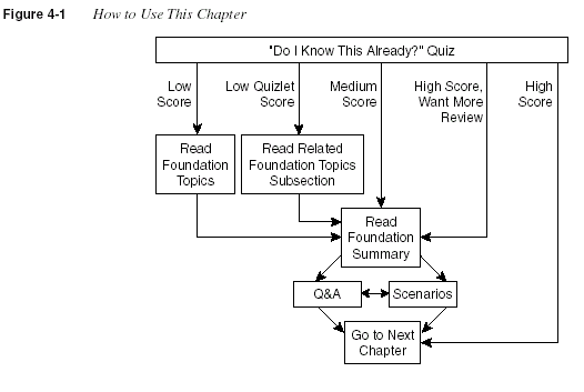
Use the diagram in Figure 4-1 to guide you to the next step.

The purpose of the “Do I Know This Already?” quiz is to help you decide what parts of this
chapter to use. If you already intend to read the entire chapter, you do not necessarily need to
answer these questions now.
This 16-question quiz helps you determine how to spend your limited study time. The quiz is
sectioned into four smaller four-question “quizlets,” which correspond to the three major
headings in the chapter. Suggestions on how to spend your time in this chapter, based on your
quiz scores, are outlined in Figure 4-1. Use Table 4-1 to record your score.
Table 4-1
Scoresheet for Quiz and Quizlets
Quizlet
Number
Foundation Topics Section Covering
These Questions Questions Score
1 LAN Overview 1 to 4
2 Bridging, Switching, and Spanning Tree 5 to 8
3 Virtual LANs 9 to 12
“Do I Know This Already?” Quiz
131
1
What do the letters MAC stand for? What other terms have you heard to describe the same
or similar concept?
___________________________________________________________________
___________________________________________________________________
___________________________________________________________________
2
What standards body owns the process of ensuring unique MAC addresses worldwide?
___________________________________________________________________
___________________________________________________________________
___________________________________________________________________
3
What is the distance limitation of 10BaseT? 100BaseTX?
___________________________________________________________________
___________________________________________________________________
___________________________________________________________________
4
How fast is Fast Ethernet?
___________________________________________________________________
___________________________________________________________________
___________________________________________________________________
5
What routing protocol does a transparent bridge use to learn about Layer 3 addressing
groupings?
___________________________________________________________________
___________________________________________________________________
___________________________________________________________________
4 LAN Switch Configuration 13 to 16
All questions 1 to 16
Table 4-1
Scoresheet for Quiz and Quizlets (Continued)
Quizlet
Number
Foundation Topics Section Covering
These Questions Questions Score
132
Chapter 4: Bridges/Switches and LAN Design
6
Name two of the methods of internal switching on typical switches today. Which provides
less latency for an individual frame?
__________________________________________________________________
__________________________________________________________________
__________________________________________________________________
7
If a switch hears three different configuration BPDUs from three different neighbors on
three different interfaces, and if all three specify that Bridge 1 is the root, how does it
choose which interface is its root port?
__________________________________________________________________
__________________________________________________________________
__________________________________________________________________
8
Assume that a building has 100 devices attached to the same Ethernet. These users then
are migrated onto two separate shared Ethernet segments, each with 50 devices, with a
transparent bridge in between. List two benefits that would be derived for a typical user.
__________________________________________________________________
__________________________________________________________________
__________________________________________________________________
9
Define the term
broadcast domain
.
__________________________________________________________________
__________________________________________________________________
__________________________________________________________________
10
Describe the benefits of creating three VLANs of 25 ports each, versus a single VLAN of
75 ports, in each case using a single switch. Assume that all ports are switched ports (each
port is a different collision domain).
__________________________________________________________________
__________________________________________________________________
__________________________________________________________________
“Do I Know This Already?” Quiz
133
11
If two Cisco LAN switches are connected using Fast Ethernet, what VLAN trunking
protocols could be used? If only one VLAN spanned both switches, is a VLAN trunking
protocol needed?
___________________________________________________________________
___________________________________________________________________
___________________________________________________________________
12
Define the term
VLAN
.
___________________________________________________________________
___________________________________________________________________
___________________________________________________________________
13
How many IP addresses must be configured for network management on a Cisco Catalyst
1900 switch if eight ports are to be used with three VLANs?
___________________________________________________________________
___________________________________________________________________
___________________________________________________________________
14
What Catalyst 1900 switch command displays the version of IOS running in the switch?
___________________________________________________________________
___________________________________________________________________
___________________________________________________________________
15
Configuration is added to the running configuration in RAM when commands are typed
in Catalyst 1900 configuration mode. What causes these commands to be saved into
NVRAM?
___________________________________________________________________
___________________________________________________________________
___________________________________________________________________
16
Name the three VTP modes. Which of these does not allow VLANs to be added or
modified?
___________________________________________________________________
___________________________________________________________________
___________________________________________________________________
134
Chapter 4: Bridges/Switches and LAN Design
The answers to the quiz are found in Appendix A, “Answers to the ‘Do I Know This Already?’
Quizzes and Q&A Sections,” on page 715. The suggested choices for your next step are as
follows:
•
8 or less overall score
—Read the entire chapter. This includes the “Foundation Topics”
and “Foundation Summary” sections and the Q&A section at the end of the chapter.
•
2 or less on any quizlet
—Review the subsection(s) of the “Foundation Topics” part of
this chapter, based on Table 4-1. Then move into the “Foundation Summary” section and
the Q&A section at the end of the chapter.
•
9 to 12 overall score
—Begin with the “Foundation Summary” section, and then go to the
Q&A section and the scenarios at the end of the chapter.
•
13 or more overall score
—If you want more review on these topics, skip to the
“Foundation Summary” section, and then go to the Q&A section at the end of the chapter.
Otherwise, move to the next chapter.
LAN Overview
135
Foundation Topics
LAN Overview
Cisco expects CCNAs to be familiar with the three types of LANs: Ethernet, Token Ring, and
FDDI. There is a bias toward questions about Ethernet, which is reasonable given the installed
base in the marketplace. For this reason, this chapter concentrates on Ethernet, with some
comments on FDDI and Token Ring, as appropriate.
Ethernet is best understood by considering the early 10Base5 and 10Base2 specifications. With
these two specifications, a bus is shared among all devices on the Ethernet, using the carrier
sense multiple access with collision detection (CSMA/CD) algorithm for accessing the bus. The
CSMA/CD algorithm works like this: The sender is ready to send a frame. The device listens
to detect whether any frame is currently being received. When the Ethernet is silent, the device
begins sending the frame. During this time, the sending device listens to ensure that the frame
it is sending does not collide with a frame that another station is sending. If no collisions occur,
the bits of the sent frame are received back successfully. If a collision has occurred, the device
sends a jam signal and then waits a random amount of time before repeating the process, again
listening to hear whether another frame is currently being received.
Because of the CSMA/CD algorithm, Ethernet 10Base5 and 10Base2 become more inefficient
under higher loads. In fact, two particular negative features of the CSMA/CD algorithm are as
follows:
•
All collided frames sent are not received correctly, so each sending station must resend the
frames. This wastes time on the bus and increases the latency for delivering the collided
frames.
•
Latency can increase for stations waiting for the Ethernet to be silent before sending their
frames. Devices must wait before sending a frame if another frame is already being sent
by another station. This increases latency while waiting for the incoming frame to
complete.
Ethernet hubs were created with the advent of 10BaseT. These hubs are essentially multiport
repeaters; they extend the bus concept of 10Base2 and 10Base5 by regenerating the same
electrical signal sent by the original sender of a frame out every other port. Therefore, collisions
can still occur, so CSMA/CD access rules continue to be used. (This is true of shared Ethernet—
switched Ethernet is covered later.) Knowledge of the operation of Ethernet cards and the
attached hub is important to have a complete understanding of the congestion problems and the
need for full-duplex Ethernet. Figure 4-2 outlines the operation of half-duplex 10BaseT with
hubs.
136
Chapter 4: Bridges/Switches and LAN Design
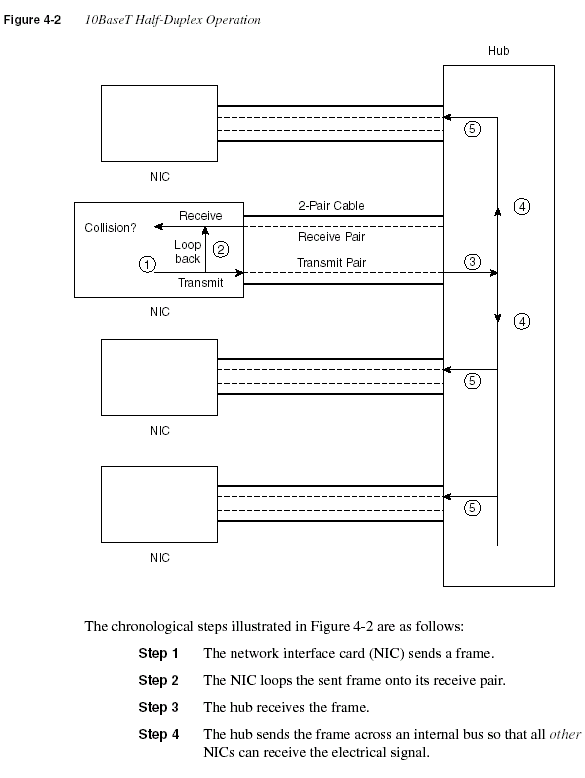
Step 5
The hub repeats the signal from each receive pair to all other
devices. In other words, the hub sends so that the attached stations
receive on their receive pair. (Similarly, the hub listens on the
transmit pair because that is the pair used by the station for
transmissions.)
Half-duplex behavior is required of all attached stations when using a shared 10BaseT
Ethernet hub, as shown in Figure 4-2. The hub has created the electrical equivalent of a bus,
so CSMA/CD rules are still in effect. Essentially, if the topology allows collisions, then
CSMA/CD is used to react to the collisions. Because CSMA/CD rules are used when collisions
could occur and half-duplex operation is required for CSMA/CD, full-duplex operation is not
possible with a shared 10BaseT hub. With a shared 10BaseT hub, if a station is receiving a
frame, it would not choose to also start sending another frame because that would cause a
collision.
Full-duplex behavior is allowed when the possibility of collisions is removed. Consider the use
of Ethernet between a pair of NICs, instead of cabling the NIC to a hub. Figure 4-3 shows the
full-duplex circuitry.

Because no collisions are possible, the NICs disable their loopback circuitry. Both ends can
send and receive simultaneously. This reduces Ethernet congestion and provides the following
advantages, as compared to half-duplex 10BaseT operation:
•
Collisions do not occur; therefore, time is not wasted retransmitting frames.
•
There is no latency waiting for others to send their frames.
•
There are 10 Mbps in each direction, doubling the available capacity (bandwidth).
Of course, if full duplex was useful only when two NICs were cabled directly to each other, as
shown in Figure 4-3, then the full duplex would not be very useful. However, full duplex is also
an option when using switches. When a single device is connected to the switch port, the switch
can ensure that there is no collision, which allows full duplex to work. If a shared hub is
connected to a switch port rather than a single device, then full duplex is not allowed because
collisions could still occur.
138
Chapter 4: Bridges/Switches and LAN Design
LAN Addressing
As a CCNA, you’ll be expected to confidently understand and interpret LAN addresses. One
important function of MAC addresses is to identify or address the LAN interface cards on
Ethernet, Token Ring, and FDDI LANs. Frames between a pair of LAN stations use a source
and destination address field to identify each other. These addresses are called
unicast
addresses
, or
individual addresses
, because they identify an individual LAN interface card.
(The term
unicast
was chosen mainly for contrast with the terms
broadcast
,
multicast
, and
group addresses
.)
Having globally unique unicast MAC addresses on all LAN cards is a goal of the IEEE, so the
organization administers a program in which manufacturers encode the MAC address onto the
LAN card, usually in a ROM chip. The first half of the address is a code that identifies the
vendor; this code is sometimes called the
Organizationally Unique Identifier
. The second part
is simply a unique number among cards that the vendor has manufactured. These addresses are
called
burned-in addresses (BIAs)
, sometimes called
Universally Administered Addresses
(UAA)
. The address used by the card can be overridden via configuration; the overriding address
is called a
Locally Administered Address (LAA)
.
Another important function of IEEE MAC addresses is to address more than one LAN card.
Group
addresses (as opposed to unicast addresses) can address more than one device on a LAN.
This function is satisfied by three types of IEEE group MAC addresses:
•
Broadcast addresses
—The most popular type of IEEE MAC address, the broadcast
address, has a value of FFFF.FFFF.FFFF (hexadecimal notation). The broadcast address
implies that all devices on the LAN should process the frame.
•
Multicast addresses
—Used by Ethernet and FDDI, multicast addresses fulfill the
requirement to address a subset of all the devices on a LAN. A station processes a received
frame with a particular multicast destination address only if configured to do so for that
multicast address. An example of multicast addresses is a range of addresses—
0100.5exx.xxxx—where different values are assigned in the last 3 bytes; these MAC
addresses are used in conjunction with Internet Group Multicast Protocol (IGMP) and IP
multicast. IP hosts on an Ethernet that want to receive IP packets to a particular IP
multicast address all use the same Ethernet MAC address, which begins with 0100.5E.
•
Functional addresses
—Valid only on Token Ring, functional addresses identify one or
more interfaces that provide a particular function. For example, c000.0000.0001 is used
by the device on a Token Ring that is currently implementing the Active Monitor function.
A subtle quirk about LAN addressing is that the order of bits in each byte of the addresses is
different between Ethernet and the other LAN types. As Figure 4-4 illustrates, the bytes are
listed in the same order; however, the bit order in each byte is opposite.
LAN Overview
139
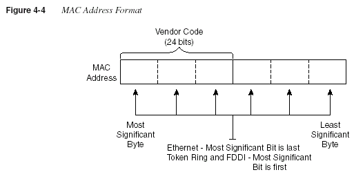
The bit order in Ethernet is called little-endian; on FDDI and Token Ring, it is called big-endian.
Let’s examine the meaning of these terms: On Ethernet, the most significant bit in a byte is
listed last in the byte. For example, assume that the binary string 01010101 is the value in a byte
of an Ethernet address. The right-most bit is considered to be the most significant bit in this
byte. However, if writing the same value in a byte of a Token Ring address, the value written
would be 10101010, so that the most significant bit is on the left. When bridging between
Ethernet and another type of LAN, the bit order in each byte of the MAC addresses must be
inverted. For example, the Token Ring address 4000.3745.0001 would be converted to
0200.ECA2.0080 before being sent onto an Ethernet.
The following list summarizes many of the key features of MAC addresses:
•
Unicast MAC addresses address an individual LAN interface card.•
Broadcast MAC addresses address all devices on a LAN.•
Multicast MAC addresses address a subset of the devices on an Ethernet or FDDI LAN.•
Functional MAC addresses identify devices performing a specific IEEE-defined function,on Token Ring only.
•
Ethernet orders the bits in each byte of the MAC address with the least significant bit first;this convention is called
little-endian.•
Token Ring and FDDI order the bits in each byte of the MAC address with the mostsignificant bit first; this convention is called
big-endian.•
The most significant bit on the first byte of an address must have a value of binary 0 forunicast addresses and 1 for broadcast, multicast, and functional addresses. This bit is
called the
broadcast bit.140
Chapter 4: Bridges/Switches and LAN Design•
The second most significant bit in the first byte of the MAC address is called the local/universal bit. A binary value of 0 implies that a burned-in or Universally Administered
Address (UAA) is being used; a binary 1 implies that a Locally Administered Address
(LAA) is being used.
LAN Framing
Figure 4-5 shows the details of LAN frames. You should remember some details about the
contents of the headers and trailers for each LAN type—in particular, the addresses and their
location in the headers. Also, the name of the field that identifies the type of header that follows
the LAN headers is important. Finally, the fact that a frame check sequence (FCS) is in the
trailer for each protocol is also vital. Figure 4-5 summarizes the various header formats.
The 802.3 specification limits the data portion of the 802.3 frame to a maximum of 1500 bytes.
The data was designed to hold some Layer 3 packets. The term
maximum transmission unit(MTU)
is used to define the maximum Layer 3 packet that can be sent over a medium; hence,with 802.3 Ethernet, 1500 is the largest MTU allowed.
The function of identifying the header that follows the LAN header (what’s in the data in Figure
4-5) is covered rather extensively in Chapter 3, “OSI Reference Model & Layered
Communication.” Any computer receiving a LAN frame needs to know what is in the data
portion of the frame. Table 4-2 summarizes the fields that are used for identifying the types of
data contained in a frame.
Table 4-2
Protocol Type Fields in LAN HeadersField Name Length LAN Type Comments
Ethernet Type 2 bytes Ethernet RFC 1700 (Assigned Numbers RFC)
lists the values. Xerox owns the
assignment process.
802.2 DSAP and SSAP 1 byte each IEEE Ethernet,
IEEE Token
Ring, ANSI
FDDI
The IEEE Registration Authority
controls the assignment of valid
values. The source SAP (SSAP) and
destination SAP (DSAP) do not have
to be equal, so 802.2 calls for the
sender’s protocol type (SSAP) and the
destination’s type (DSAP).
SNAP Protocol 2 bytes IEEE Ethernet,
IEEE Token
Ring, ANSI
FDDI
Uses EtherType values. Used only
when DSAP is hex AA. It is needed
because the DSAP and SSAP fields
are only 1 byte in length.
LAN Overview
141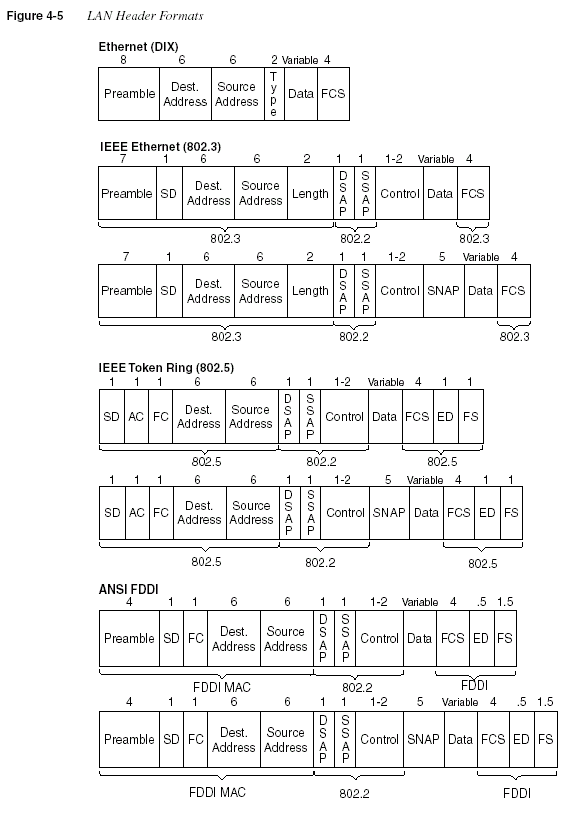
142
Chapter 4: Bridges/Switches and LAN DesignSome examples of values in the Ethernet Type and SNAP Protocol fields are: 0800 for IP and
8137 for NetWare. Examples of IEEE SAP values are: E0 for NetWare, 04 for SNA, and AA
for SNAP.
Fast Ethernet and Gigabit Ethernet
The two key additional features of Fast Ethernet, as compared to 10-Mbps Ethernet, are higher
bandwidth and autonegotiation. Autonegotiation allows an Ethernet card, hub, or switch to
determine which type of 100-Mbps Ethernet is supported by the device, hub, or switch on the
other end of the cable. Also, support for half duplex or full duplex is negotiated. If the other
device, such as a 10BaseT NIC, does not support autonegotiation, then autonegotiation will
settle for half-duplex 10BaseT.
Fast Ethernet retains many familiar features of 10-Mbps Ethernet variants. The age-old
CSMA/CD logic still exists and can be disabled for full-duplex point-to-point topologies in
which no collisions can occur. A variety of cabling options is allowed—unshielded and shielded
copper cabling, as well as multimode and single-mode fiber. Both Fast Ethernet shared hubs and
switches can be deployed. However, because Fast Ethernet gained market acceptance around
the same time that LAN switching became popular, most Fast Ethernet cards either are
connected to a switch or are directly cabled to another device.
Gigabit Ethernet also retains many familiar features of slower Ethernet variants. CSMA/CD is
still used and can still be disabled for full-duplex support. Although gigabit hubs are allowed,
it is more likely that Gigabit Ethernet switch ports will be the most popular use for Gigabit
Ethernet, along with use as a trunk between high-throughput switches and routers.
The biggest differences between Gigabit Ethernet and its slower cousins are the obvious speed
difference and the use of a different physical layer. The physical layer differences are truly
beyond the scope of the CCNA exam, but the history is interesting. To improve speed to market,
the specifications call for the use of a slightly changed FibreChannel physical layer (ANSI
X3T11) to operate at 1.25 gigabaud. An 8B/10B encoding scheme, which transmits a 10-bit
energy signal (baud) that represents an 8-bit value, is used. (The concept of the 8B/10B
encoding is not terribly different from FDDI’s 4B/5B encoding.) The net result is that 8 bits are
exchanged per baud; at 1.25 gigabaud, 1 Gbps is achieved.
Both Fast Ethernet (FE) and Gigabit Ethernet (GE) relieve congestion in some fairly
obvious ways. Collisions and wait time are decreased when compared to 10-Mbps Ethernet,
simply because it takes 90 percent (FE) or 99 percent (GE) less time to transmit the same
frame on the faster LANs. Capacity is greatly increased as well: If all frames were 1250 bytes
long, a 10,000 frames per second theoretical maximum could be reached on Fast Ethernet, and
a 100,000 frames per second theoretical maximum could be reached on Gigabit Ethernet. (Of
course, this little math problem ignores such details as interframe gaps and the unlikely case
of identical length frames; they’re listed here for perspective.)
LAN Overview
143Autonegotiation uses a priority scheme to define the more preferred options for Fast and
10-Mbps Ethernet. The lower the priority value, the more preferred the specification. The
names of these standards are listed in Table 4-3, along with the priority used by the
autonegotiation process.
Autonegotiation uses a series of Fast Link Pulses (FLPs) to communicate with the device on
the other end of the cable. An exchange takes place as to what each endpoint is capable of
supporting. The Autonegotiation Priority in Table 4-3 shows the choice that the process would
make if more than one option was supported—of the supported options, the one with the lowest
autonegotiation priority is the option chosen.
The autonegotiation process has been known to fail. Cisco recommends that for more important
devices, you should configure the LAN switch to the correct setting rather than depend on
autonegotiation.
LAN Standards
Cisco expects CCNAs to be very familiar with Ethernet specifications, as well as be familiar
with the basics of FDDI and Token Ring standards. The IEEE defines most of the standards
for Ethernet and Token Ring, with ANSI defining standards for FDDI. Table 4-4 lists the
specification that defines the Media Access Control (MAC) and Logical Link Control (LLC)
sublayers of the three LAN types for comparison.
Table 4-3
100Bx Standards and Autonegotiation PriorityStandard Full or Half Duplex Autonegotiation Priority
100BaseT2 Full 1
100BaseT2 Half 2
100BaseTX Full 3
100BaseTX Half 4
100BaseT4 Half 5
10BaseT Full 6
10BaseT Half 7
Table 4-4
MAC and LLC Details for Three Types of LANsName
MAC Sublayer
Spec
LLC Sublayer
Spec Other Comments
Ethernet Version 2
(DIX Ethernet)
Ethernet Not applicable This spec is owned by Digital,
Intel, and Xerox.
IEEE Ethernet IEEE 802.3 IEEE 802.2 This is also popularly called
802.3 Ethernet.
continues
144
Chapter 4: Bridges/Switches and LAN DesignWith the advent of Fast Ethernet and Gigabit Ethernet, the variety of Ethernet standards has
increased to the point that most networking personnel do not memorize all the standards.
However, the CCNA exam will require you to be very familiar with Ethernet standards,
or at least the standards for 10- and 100-Mbps Ethernet. Table 4-5 lists the key Ethernet
specifications and several related details about the operation of each.
1. For entire bus, without using a repeater
2. From device to hub/switch
3. Numbers shown are for half or full duplex
Token Ring IEEE 802.5 IEEE 802.2 IBM helped with development
before the IEEE took over.
FDDI ANSI X3T9.5 IEEE 802.2 ANSI liked 802.2, so it just
refers to the IEEE spec.
Table 4-5
Ethernet StandardsStandard
MAC Sublayer
Specification
Maximum Cable
Length Cable Type
Pairs
Required
10Base5 802.3 500 m
1 50-Ohm thick coaxialcable
—
10Base2 802.3 185 m
1 50-Ohm thin coaxialcable
—
10BaseT 802.3 100 m
1 Category 3, 4, or 5UTP
2
10BaseFL 802.3 2000 m
2 Fiber 1100BaseTx 802.3u 100 m
2 Category 5 UTP 2100BaseT4 802.3u 100 m
2 Category 3 UTP 4100BaseT2 802.3u 100 m
2 Category 3, 4, or 5UTP
2
100BaseFx 802.3u 400/2000 m
3 Multimode fiber 1100BaseFx 802.3u 10,000m Single-mode fiber 1
1000BaseSx 802.3z 220-550m Multimode fiber 1
1000BaseLx 802.3z 3000m Single-mode or
multimode fiber
1
1000BaseCx 802.3z 25m Shielded copper 2
1000BaseT 802.3ab 100m Category 5 UTP 2
Table 4-4
MAC and LLC Details for Three Types of LANs (Continued)Name
MAC Sublayer
Spec
LLC Sublayer
Spec Other Comments
Bridging, Switching, and Spanning Tree
145For more information on Fast Ethernet and information on Gigabit Ethernet, try the following
Web pages:
•
wwwhost.ots.utexas.edu/ethernet/ethernet-home.html•
www.ots.utexas.edu/ethernet/descript-100quickref.html•
www.iol.unh.edu/training•
www.cisco.com/warp/customer/cc/cisco/mkt/switch/fasteth/tech/feth_tc.htm•
www.cisco.com/warp/customer/cc/cisco/mkt/switch/gig/tech/index.shtml•
www.gigabit-ethernet.orgBridging, Switching, and Spanning Tree
Transparent bridging and LAN switching are two topics you must understand to succeed on the
CCNA exam. The underlying logic between the two is very similar, so both are described in this
section. The Spanning-Tree Protocol, which prevents loops from occuring in a bridged/
switched network, is described after bridging and switching basics are completed. Finally, a
comparison of what happens when a single Ethernet is migrated to a pair of Ethernets—
separated by a bridge in one case, a switch in another case, and a router in the third case—serves
as a good review of the concepts behind all three types of campus forwarding devices.
The IOS also supports other types of bridging, namely source-route bridging (SRB), sourceroute
transparent bridging (SRT), and source-route translational bridging (SR/TLB). Cisco
expects CCNAs to be familiar with transparent bridging.
Transparent Bridging
Transparent bridging is called transparent because the endpoint devices do not need to know
that the bridge(s) exists. In other words, the computers attached to the LAN do not behave any
differently in the presence or absence of transparent bridges.
Transparent bridging is the process of forwarding frames, when appropriate. To accomplish
this, transparent bridges perform three key functions:
•
Learning MAC addresses by examining the source MAC addresses of each frame receivedby the bridge
•
Deciding when to forward a frame and when to filter a frame, based on the destinationMAC address
•
Creating a loop-free environment with other bridges using the Spanning-Tree Protocol146
Chapter 4: Bridges/Switches and LAN DesignTo fully understand transparent bridging logic, consider Figure 4-6. A client first asks for a DNS
name resolution and then connects to a Web server. All three devices are on the same LAN
segment. ARP requests are used to find the MAC addresses of the DNS and the Web server.
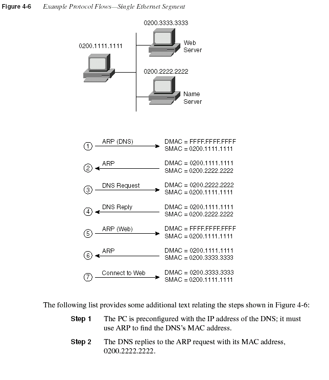
Step 3
The PC requests name resolution by the DNS for the Web server’sname.
Step 4
The DNS returns the IP address of the Web server to the PC.Step 5
The PC does not know the Web server’s MAC address, but it doesknow its IP address, so the PC sends an ARP broadcast to learn the
MAC address of the Web server.
Step 6
The Web server replies to the ARP, stating that its MAC address is0200.3333.3333.
Step 7
The PC can now send frames directly to the Web server.Now consider the same protocol flow, but with the DNS on a separate segment and a transparent
bridge separating the segments, as shown in Figure 4-7. The computers act no differently,
sending the same frames and packets. The transparent bridge forwards all broadcasts, all unicast
destination frames not in its bridge table, and multicasts.
Figure 4-7 illustrates several important ideas related to segmentation. The ARP requests in
Steps 1 and 5 are forwarded by the bridge because they are broadcasts. Likewise, requests from
the client to and from the DNS are forwarded. However, the rest of the frames from the client
to the Web server and back are not forwarded by the bridge because the bridge knows that both
MAC addresses (client and Web server MACs) are on the same Ethernet as its E0 interface.
Also, because there is no redundant path through other bridges, there is no need to use the
Spanning-Tree Protocol to block interfaces and limit the flow of frames.
Some characterizations of transparent bridge behavior, as compared to a single segment with
no bridges, are listed here:
•
Broadcasts and multicast frames are forwarded by a bridge.•
Transparent bridges perform switching of frames using Layer 2 headers and Layer 2 logicand are Layer 3 protocol-independent. This means that installation is simple because no
Layer 3 address group planning or address changes are necessary. For example, because
the bridge retains a single broadcast domain, all devices on all segments attached to the
bridge look like a single subnet.
•
Store-and-forward operation is typical in transparent bridging devices. Because an entireframe is received before being forwarded, additional latency is introduced (as compared
to a single LAN segment).
•
The transparent bridge must perform processing on the frame, which also can increaselatency (as compared to a single LAN segment).
148
Chapter 4: Bridges/Switches and LAN Design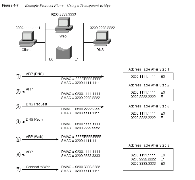
LAN Switching
An Ethernet switch appears to use the same logic as a transparent bridge. However, the internal
logic of the switch is optimized for performing the basic function of choosing when to forward
and when to filter a frame. Just as with a transparent bridge, the basic logic of a LAN switch is
as follows:
Step 1
A frame is received.Step 2
If the destination is a broadcast or multicast, forward on all ports.Bridging, Switching, and Spanning Tree
149Step 3
If the destination is a unicast and the address is not in the addresstable, forward on all ports.
Step 4
If the destination is a unicast and the address is in the addresstable, forward the frame out the associated port, unless the MAC
address is associated with the incoming port.
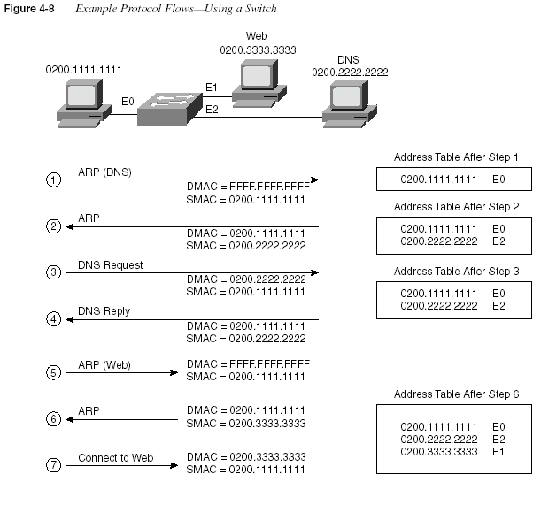
Consider Figure 4-8, which separates LANs with a switch.
150
Chapter 4: Bridges/Switches and LAN DesignThe following list provides some additional insights relating to the steps shown in Figure 4-8:
Step 1
The PC is preconfigured with the IP address of the DNS. The PCnotices that the DNS IP address is in the same subnet as its own IP
address; therefore, the PC sends an ARP broadcast hoping to learn
the DNS’s MAC address.
Step 2
The DNS replies to the ARP request with its MAC address,0200.2222.2222.
Step 3
The PC requests name resolution for the Web server by sending apacket with the destination IP address of the DNS.
Step 4
The DNS returns the IP address of the Web server to the PC in theDNS reply.
Step 5
The PC does not know the Web server’s MAC address, so it sendsan ARP broadcast to learn the MAC address. Because it is a MAC
broadcast, the switch forwards the frame on all ports.
Step 6
The Web server replies to the ARP, stating that its MAC address is0200.3333.3333.
Step 7
The PC can now connect to the Web server.The two ARP broadcasts (Steps 1 and 5) are sent out all switch ports because switches and
bridges do not perform the
broadcast firewall function that a router performs. After theswitching table (often called the address table) is built, the switch forwards unicasts only out of
the appropriate ports. In other words, frames sent from the client to the Web server, and vice
versa (which are unicasts), are never sent out port E2.
The switch network has created three separate Ethernet segments, as compared to the
transparent bridge network in Figure 4-7, which creates two LAN segments. Each segment is
called a
collision domain because frames sent by any device on that segment could collide withother frames on the segment. Switches can be used to create many collision domains.
Another feature of switches is that they forward broadcasts and multicasts on all ports.
However, they reduce the impact of collisions because devices on separate switch ports are on
separate Ethernet segments (which are separate collision domains). This behavior of switches
resulted in the creation of the terms
collision domain and broadcast domain. Figure 4-9 showsa network with six collision domains—six sets of interface cards for which CSMA/CD logic is
used to share the LAN segment.
Each collision domain is separated by either a transparent bridge, a switch, or a router. The
figure suggests that the segments on either side of the bridge could be 10Base2, 10Base5, or any
shared hub. The segment between the router and switch, and between the switch and the PCs
on the right, can be a single cable, as shown. In either case, if a bridge (transparent bridge or
switch) or routing function separates devices, the devices are in separate collision domains.
Bridging, Switching, and Spanning Tree
151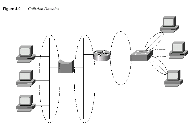
NOTE
Many vendors, including Cisco, sell cards in switches that do not switch on all ports. In otherwords, the equivalent of a shared hub with several ports is built into a card rather than each port
being treated as its own collision domain. Frames destined for a MAC address off one of these
ports are sent out all these ports by the switch. The switch ports in the figures in this chapter are
all switched, unless otherwise specified.
The broadcast domain concept is similar to the concept of collision domains; however, only
routers stop the flow of broadcasts. Figure 4-10 provides the broadcast domains for the same
network depicted in Figure 4-9.
The broadcast domain is not affected by the inclusion or exclusion of switches or bridges. The
router creates its own broadcasts (RIP, IGRP, SAP, and so on), but the router does not forward
broadcasts received in the left-side interface out the right-side interface. In other words,
broadcasts created and sent by a device in one broadcast domain are not sent to devices in
another broadcast domain.
152
Chapter 4: Bridges/Switches and LAN Design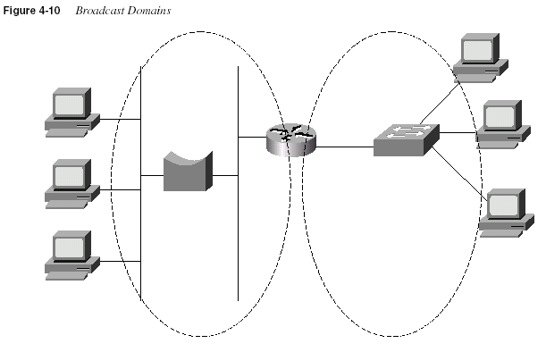
General definitions for collision domain and broadcast domain are as follows:
A
collision domain is a set of interface cards (NICs) for which a frame sent by one NICcould result in a collision with a frame sent by any other NIC in the collision domain.
A
broadcast domain is a set of NICs for which a broadcast frame sent by one NIC will bereceived by all other NICs in the broadcast domain.
Layer 3 addressing is affected whenever a router is added to a network. For example, if only
bridges and switches had existed in the network in Figure 4-10, and if the router was later
added, Layer 3 IP and IPX addresses would have changed. To use the terminology in Chapter
3, two separate address groupings (for example, IP subnets) would be used for IP—one for the
devices to the left of the router and another for devices to the right of the router. A definition of
Layer 3 address groupings on LANs will help you understand VLANs better:
NOTE
All devices in the same broadcast domain (Layer 2) will be in the same Layer 3 addressgrouping—in other words, the same IP subnet or same IPX network.
The internal processing on the switch can decrease latency for frames. Transparent bridges use
store-and-forward processing, meaning that the entire frame is received before the first bit of
Bridging, Switching, and Spanning Tree
153the frame is forwarded. Switches can use store-and-forward as well as cut-through processing
logic. With cut-through processing, the first bits of the frame are sent out the outbound port
before the last bit of the incoming frame is received instead of waiting for the entire frame to
be received. In other words, as soon as the switching port receives enough of the frame to see
the destination MAC address, the frame is transmitted out the appropriate outgoing port to the
destination device. The unfortunate side effect is that because the frame check sequence (FCS)
is in the Ethernet trailer, the forwarded frame may have bit errors that the switch would have
noticed with store-and-forward logic. And, of course, if the outbound port is busy, the switch
will store the frame until the port is available.
The internal processing algorithms used by switches vary among models and vendors;
regardless, the internal processing can be categorized as one of the methods listed in Table 4-6.
Full Duplex and Switches
Frames can be forwarded concurrently through a switch. Consider Figure 4-11, with Fred
sending a frame to Wilma, and Barney sending a frame to Betty.
In this figure, the switch forwards the frame coming in Port 1 out Port 3 and does the same for
the frame coming in Port 2 and out Port 4. These frames also are in four different collision
domains. For these reasons, no collision occurs. A four-port transparent bridge would behave
the same way, but switches are optimized for concurrent frame forwarding, so latency is likely
to be less with a switch.
In conjunction with switches, full-duplex Ethernet can add other benefits. Figure 4-12 shows a
server (Pebbles) that is both sending and receiving a frame at the same time. Betty and Wilma
are in different collision domains, so Pebbles cannot undergo a collision due to the nature of
full-duplex Ethernet.
Table 4-6
Switch Internal ProcessingSwitching Method Description
Store-and-forward The switch fully receives all bits in the frame (store) before forwarding the
frame (forward). This allows the switch to check the FCS before forwarding
the frame. (FCS is in the Ethernet trailer.)
Cut-through The switch performs the address table lookup as soon as the destination
address field in the header is received. The first bits in the frame can be sent
out the outbound port before the final bits in the incoming frame are
received. This does not allow the switch to discard frames that fail the FCS
check. (FCS is in the Ethernet trailer.)
FragmentFree This performs like cut-through, but the switch waits for 64 bytes to be
received before forwarding the first bytes of the outgoing frame. According
to Ethernet specifications, collisions should be detected during the first 64
bytes of the frame; frames in error due to collision will not be forwarded.
The FCS still cannot be checked.
154
Chapter 4: Bridges/Switches and LAN Design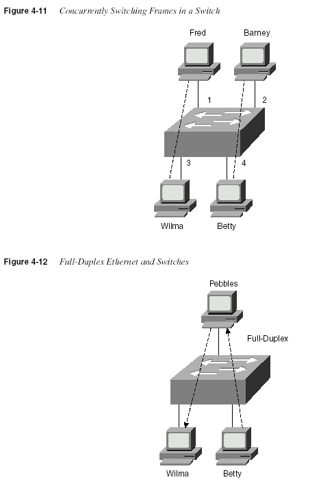
Bridging, Switching, and Spanning Tree
155Comparison of LAN Segmentation Using Bridges, Switches, and
Routers
Cisco expects CCNAs to have command of the tradeoffs involved when designing campus
LANs. One key consideration is to understand the different behavior when separating, or
segmenting, LAN segments with some switching device. All the concepts related to LAN
segmentation using bridges, switches, and routers are included in other parts of this chapter or
in other chapters. However, the comparisons made in this section are important and would be
missed if this book simply covered the technical content when covering bridging, switching,
and routing.
The basic workings of a bridge and a switch have already been covered in this chapter. For
review, routing logic is covered first, followed by a comparison of segmentation using the three
different device options.
Routing is covered more fully in other chapters. For comparison, the same example flow of a
client connecting to a Web server is shown, this time with a router separating two Ethernet
segments. This same example is shown for bridging and switching earlier in this chapter. Figure
4-13 illustrates a couple of key features of routing.
The flows in the figure match the numbers in this list, which explains the meaning and
implications of the flows in the figure:
Step 1
The PC is preconfigured with the IP address of the DNS. The PCnotices that the IP address is on a different subnet, so the PC wants
to forward the packet to its default router. However, the PC does
not know its default router’s MAC address yet, so it must use ARP
to find that router’s MAC address.
Step 2
The router replies to the ARP request with its MAC address,0200.4444.4444.
Step 3
The PC requests name resolution for the Web server by sending apacket with the destination IP address of the DNS. The destination
MAC address in the frame sent by the PC is the router’s E0 MAC
address. The router receives the frame, extracts the packet, and
forwards it.
Step 4
The DNS returns the IP address of the Web server to the PC in theDNS reply.
Step 5
The PC does not know the Web server’s MAC address, so it sendsan ARP broadcast to learn the MAC address. The router has no
need to forward the ARP broadcast.
Step 6
The Web server replies to the ARP, stating that its MAC address is0200.3333.3333.
Step 7
The PC can now connect to the Web server.156
Chapter 4: Bridges/Switches and LAN Design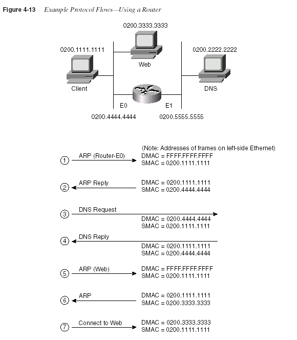
The ARP broadcasts are not forwarded by the router. In fact, the logic in Step 1 begins with an
ARP looking for the MAC address of the client’s default router—namely, the router’s E0 MAC
address. This broadcast was not forwarded by the router, a fact that causes a router to be called
a
broadcast firewall. Comparing this to a transparent bridge or a LAN switch, this difference inbroadcast treatment is the biggest advantage of routers.
Bridging, Switching, and Spanning Tree
157Table 4-7 lists several features relating to segmenting LANs with bridges, switches, and routers.
Essentially, this chart summarizes features that could differ among the three devices. Table 4-8
lists features that describe how each device performs when compared to using a single Ethernet
segment with no bridge, switch, or router. The two tables together provide the necessary details
when comparing the three types of devices.
1. Routers can forward IP multicast packets, if configured to do so. However, this does not mean that the LAN
multicast frame is forwarded.
Table 4-8 lists features that should be interpreted within the following context: “If I migrated
from a single Ethernet segment to a network with two segments separated by a bridge/switch/
router, and if traffic loads and destinations stayed constant, the result would be _______.”
Table 4-7
Comparison of Segmentation OptionsFeature Bridging Switching Routing
Forwards LAN broadcasts? Yes Yes No
Forwards LAN multicasts? Yes Yes; can be
optimized with
CGMP
No
1OSI layer used when making forwarding
decision
Layer 2 Layer 2 Layer 3
Internal processing variants Store-andforward
Store-andforward,
cutthrough,
FragmentFree
Store-andforward
Frame/packet fragmentation allowed? No No Yes
Multiple concurrent equal-cost paths to
same destination allowed?
No No Yes
Table 4-8
Comparison of a Single Segment to Multiple SegmentsFeature Bridging Switching Routing
Greater cabling distances allowed Yes Yes Yes
Decrease in collisions, assuming equal
traffic loads
Yes Yes Yes
Decreased adverse impact of broadcasts No No Yes
Decreased adverse impact of multicasts No Yes, with CGMP Yes
Increase in bandwidth Yes Yes Yes
Filtering on Layer 2 header allowed Yes Yes Yes
Filtering on Layer 3 header allowed No No Yes
158
Chapter 4: Bridges/Switches and LAN DesignCertainly, the most important distinction among the three segmentation methods is their
treatment of broadcasts and multicasts. Remembering the concepts of collision domains,
broadcast domains, and how each device separates LANs into different domains is one key to
understanding campus LAN design and troubleshooting.
Spanning Tree
The Spanning-Tree Protocol is an important topic for a true understanding of bridged and
switched networks. A thorough understanding of Spanning Tree also is important for CCNP and
CCIE certification; the basics are required for CCNA certification.
NOTE
Two wonderful sources of information can help you learn more about the Spanning-TreeProtocol. One is a book by Radia Perlman called
Interconnections: Bridges, Switches, andRouters
. The other is the Cisco Press book Cisco LAN Switching, by Kennedy Clark and KevinHamilton. Both books cover Spanning Tree in a clear and detailed manner; the Cisco Press book
also covers implementation details on Cisco’s LAN switching products. Perlman’s book has
been a long-time favorite of mine, but the Clark and Hamilton book has recently been added to
my list of top five favorite (computer) books.
The purpose of the Spanning-Tree Protocol is to dynamically create a bridged/switched
network in which only one active path exists between any pair of LAN segments (collision
domains). To accomplish this task, all bridging devices, including switches, use a dynamic
protocol. The result of the protocol is that each interface on a bridging device will settle into a
blocking
state or a forwarding state. Blocking means that the interface cannot forward orreceive data frames, but it can send and receive Configuration Bridge Protocol Data Units
(CBPDUs); forwarding means the interface can both send and receive data frames. By having
a correct subset of the interface’s block, a single currently active logical path will exist between
each pair of LANs.
NOTE
For the rest of this chapter, the terms bridge and bridging device refer to a device that can be atransparent bridge or a LAN switch. If a distinction between the two needs to be made, the terms
transparent bridge
or switch will be used.Figure 4-14 demonstrates the obvious need for a loop-free path between segments. Frames
destined for unknown MAC addresses, or broadcasts, will be forwarded infinitely by the
bridges.
Bridging, Switching, and Spanning Tree
159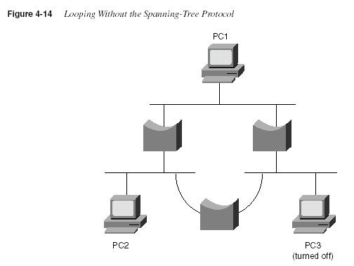
Frames addressed to PC3’s MAC address will loop forever—or at least until time is no more!
No mechanism defined in Ethernet marks the frame to be thrown away by a bridge, similar to
the way an IP router uses the time-to-live field. The frame destined to PC3 would be forwarded
because the bridges do not have PC3’s MAC address in their bridge tables. Similarly, bridges
forward broadcasts on all interfaces, so if PC1 or PC2 sent a broadcast, the broadcast would
loop for a long time.
Of course, having only one physical path between segments is a poor design for availability. If
any part of that one path failed, the network would be broken into separate parts whose devices
could not communicate. So, there is a need for physical redundancy, but with only one active
path because transparent bridging logic will not tolerate multiple active paths. The solution is
to build bridged networks with physical redundancy and to use Spanning Tree to dynamically
block some interface(s) so that
only one active path exists at any instant in time.Finally, any possibility of loops occurring during the process of converging to a new Spanning
Tree must be avoided. Consider Figure 4-15, particularly Bridges 4 and 5. If a loop occurred in
this network, frames would rotate forever and the number of frames would grow. A frame on
either segment that both Bridges 4 and 5 are attached to would be forwarded by both bridges,
duplicating the frames. In a few short seconds, all LAN segments would be filled with copies
of the frames that occurred during the loop, possibly preventing the Spanning-Tree Protocol
from completing its task of re-creating the loop-free environment.
160
Chapter 4: Bridges/Switches and LAN Design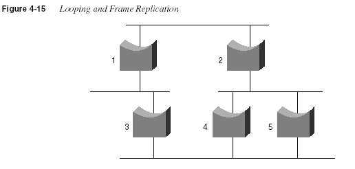
To sum up, the benefits of the Spanning-Tree Protocol are as follows:
•
Physically redundant paths in the network are allowed to exist and be used when otherpaths fail.
•
Bridging logic is confused by multiple active paths to the same MAC address; Spanning-Tree Protocol avoids this by creating only one path.
•
Loops in the bridged network are avoided.How the Spanning-Tree Protocol Works
The Spanning-Tree Algorithm results in each bridge interface being placed into either a
forwarding state or a blocking state. Interfaces in forwarding state are considered to be in the
current Spanning Tree; those in blocking state are not considered to be in the tree. The algorithm
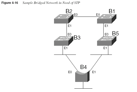
is elegant but basic. Figure 4-16 illustrates a network with physical redundancy, which will need
to use STP.
The setup in Figure 4-16 uses four switches (B1, B2, B3, and B5) and one transparent bridge.
A variety of bridges and switches are shown to make the point that both Ethernet switches and
transparent bridges use Spanning Tree.
The key to the algorithm is that the set of all forwarding interfaces (those in the tree) form one
path through the LAN segments (collision domains), assuming that at least one physical path is
available. Three criteria are used to place an interface into forwarding mode:
•
All interfaces on the root bridge are in forwarding state.•
Each nonroot bridge considers one of its ports to have the least administrative costbetween itself and the root bridge. This interface, called that bridge’s
root port, is placedinto a forwarding state.
•
Many bridges can attach to the same segment. These bridges advertise ConfigurationBridge Protocol Data Units (CBPDUs) declaring their administrative cost to the root
Bridging, Switching, and Spanning Tree
161bridge. The bridge with the lowest such cost of all bridges on that segment is called the
designated bridge
. The interface on the designated bridge on that segment is placed in aforwarding state.
All other interfaces are placed in a blocking state. Table 4-9 summarizes the reasons why
Spanning Tree places a port in forwarding or blocking state:
Table 4-9
Spanning Tree: Reasons for Forwarding or BlockingCharacterization of Port Spanning Tree State Explanation
All root bridge’s ports Forwarding The root bridge is always the
designated bridge on all
connected segments.
Each nonroot bridge’s root port Forwarding The root port is the port
receiving the lowest-cost
CBPDU from the root.
Each LAN’s designated bridge Forwarding The bridge forwarding the
lowest-cost CBPDU onto the
segment is the designated
bridge.
All other ports Blocking The port is not used for
forwarding frames, nor are any
frames received on these
interfaces considered for
forwarding.
162
Chapter 4: Bridges/Switches and LAN DesignBuilding an Initial Spanning Tree
Each bridge begins by claiming to be the root bridge. The Spanning-Tree Protocol defines
messages used to exchange information with other bridges. These messages are called
Configuration Bridge Protocol Data Units (CBPDUs)
. Each bridge begins by sending aCBPDU stating the following:
•
The root bridge’s bridge ID. This is typically a MAC address on one of the bridge’sinterfaces. Each bridge sets this value to its own bridge ID.
•
An administratively set priority.•
The cost between the bridge sending this CBPDU and the root. At the beginning of theprocess, each bridge claims to be root, so the value is set to 0.
•
The bridge ID of the sender of this CBDPU. At the beginning of the process, each bridgeclaims to be root, so this ID is the same as the root bridge’s ID.
The root bridge will be the bridge with the lowest priority value. If a tie occurs based on priority,
the root bridge with the lowest ID will be the root. The bridge IDs should be unique because
MAC addresses are supposed to be unique.
The process of choosing the root begins with all bridges claiming to be the root by sending
CBPDUs with their bridge IDs and priorities. If a bridge hears of a better candidate, it stops
advertising itself as root and starts forwarding the CBPDUs sent by the better candidate. Before
forwarding that CBPDU, the bridge increments the cost by a value based on a cost setting of
the interface on which the better candidate’s CBPDU was received. It’s almost like a political
race, with candidates dropping out once they cannot win and throwing their support behind the
best candidate. At the end of the election, the best candidate wins. Figure 4-17 outlines what the
bridges do after the process has settled. Table 4-10 lists the different costs used on each
interface.
Given the scenario in Figure 4-17, Bridge 2 adds its E0 cost (100) to the cost of the CBPDU
from Bridge 1 (root = Bridge 1, cost = 0), so Bridge 2 considers its cost to the root to be 100.
However, Bridge 2 does not send a CBPDU out its E0 port because that is the port in which the
CBPDU about the best root candidate entered. Instead, Bridge 2 advertises a CBPDU only out
its other ports. Bridge 3 receives the CBPDU from Bridge 2 and adds the port cost of the
incoming port, its E0 port, to the cost. Bridge 3 considers its cost to the root to be 200, as
reflected in its CBPDU.
Consider the steady-state CBPDU messages from Bridge 4’s perspective. This bridge receives
a CBPDU about Bridge 1 as root from both Bridge 3 and Bridge 5. The cost in the CBPDU from
Bridge 5 is lower; therefore, that is the message to which Bridge 4 reacts. Following the same
logic, Bridge 4 adds its E1 port cost to the cost learned from Bridge 5, leaving a total of 110.
Bridge 4 sends a CBPDU out all other ports besides its E1 port.
Bridging, Switching, and Spanning Tree
163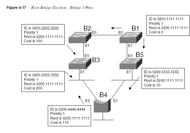
* Signifies the values that affected the cost values in the CBPDUs
Table 4-10
Bridge Cost ValuesBridge Interface Cost
Bridge 1, E0 100
Bridge 1, E1 10
Bridge 2, E0 * 100
Bridge 2, E1 100
Bridge 3, E0 * 100
Bridge 3, E1 10
Bridge 4, E0 10
Bridge 4, E1 * 100
Bridge 5, E0 * 10
Bridge 5, E1 100
164
Chapter 4: Bridges/Switches and LAN DesignOf course, the creation of the Spanning Tree causes some interfaces to forward and others to
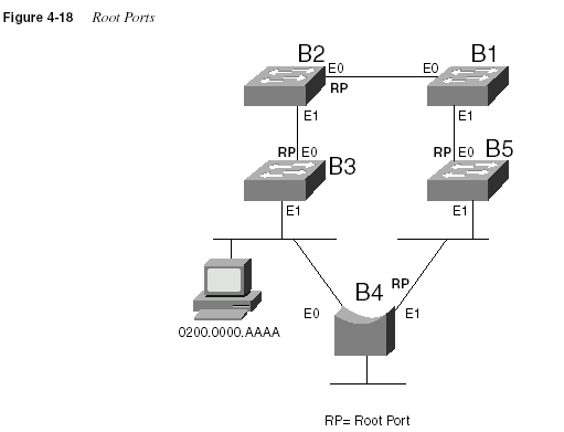
block, which is the goal. Both ports on Bridge 1 will be in a forwarding state. The interface in
which the other bridges receive their lowest-cost CBPDU about the root is considered to be
their root port. Figure 4-18 shows the root ports with a simple designation of RP.
The final step in the process is for each bridge to decide whether to forward or block on its
nonroot ports. Each LAN has one bridge that is sending the CBPDU about the root with the
least cost. Referring to Figure 4-17, the segment to which Bridge 3 and Bridge 4 are attached
shows Bridge 4 advertising the lower cost (110). Bridge 4 is then considered to be the
designated bridge
on that LAN segment, so Bridge 4 places its E0 port into forwarding state.On the other LAN segments, only one bridge is sending CBPDUs, so it is obvious which bridge
will be designated bridge on each of those segments—Bridge 2’s E1 port and Bridge 5’s E1 port
will be placed into forwarding state as well.
The process is now complete, with all ports in forwarding state except for Bridge 3’s E1
interface. Table 4-11 outlines the state of each port and shows why it is in that state.
Bridging, Switching, and Spanning Tree
165Noticing and Reacting to Changes in Network Topology
A periodic notice is sent to tell all bridges that nothing has changed in the network. The protocol
mechanism begins when the root sends CBPDUs on all its interfaces with the same information
in it as before: its bridge ID, priority, cost (0), and the root bridge ID, which is itself. As seen in
Figure 4-17, the bridges receive the CBPDUs, adjust the cost, and send the CBPDUs on all
interfaces except their root ports.
The CBPDU created by the root also includes some important timers:
•
Hello time—The time that the root waits before resending the periodic CBPDUs, whichare then forwarded by successive bridges.
•
MaxAge—The time any bridge should wait before deciding that the topology haschanged.
•
Forward Delay—Delay that affects the time involved when an interface changes from ablocking state to a forwarding state; this timer will be covered in more depth shortly.
The MaxAge timer is typically a multiple of Hello. This allows some CBPDUs to be lost,
without the bridges reacting and changing the Spanning Tree. The MaxAge setting should also
consider the variations in how long it takes the CBPDUs to traverse the network. In a local
environment, these variations should be minimal unless severe congestion causes a large
number of frames to be discarded.
Table 4-11
The State of Each InterfaceBridge Interface State
Reason Interface Is in
Forwarding State
Bridge 1, E0 Forwarding Interface is on root bridge
Bridge 1, E1 Forwarding Interface is on root bridge
Bridge 2, E0 Forwarding Root port
Bridge 2, E1 Forwarding Designated bridge
Bridge 3, E0 Forwarding Root port
Bridge 3, E1 Blocking Not root bridge, not root port, no designated
bridge
Bridge 4, E0 Forwarding Designated bridge
Bridge 4, E1 Forwarding Root port
Bridge 5, E0 Forwarding Root port
Bridge 5, E1 Forwarding Designated bridge
166
Chapter 4: Bridges/Switches and LAN DesignWhen the network is up and no problems are occurring, the process works like this:
Step 1
The root sends a CBPDU, cost 0, out all its interfaces.Step 2
The neighboring bridges send CBPDUs out their nonroot portinterfaces referring to the root, but with their cost added.
Step 3
Step 2 is repeated by each bridge in the network as it receives theseCBPDUs, as long as the CBPDU is received on a bridge’s root
port.
Step 4
The root repeats Step 1 every Hello time.Step 5
If a bridge does not get a CBPDU in Hello time, it continues asnormal, unless the larger MaxAge timer is passed.
Reacting to Changes in the Spanning Tree
The process used to react to changes in topology varies depending on the situation. This section
describes two instances, one briefly and the other in detail. Other variations than the two
instances covered here do occur. Regardless of the details, the process always begins when a
bridge does not receive a CBPDU on its root port in MaxAge time.
No CBPDUs Received on Any Ports
If the bridge whose MaxAge parameter expires is also not receiving any other CBPDUs on
ports that are not the root port, that bridge reacts by claiming to be the root bridge and begins
sending CBPDUs describing itself. This process reduces to the same logic as described earlier
in the section “Building an Initial Spanning Tree.”
For instance, imagine that the root bridge failed in the network in Figure 4-17. Each bridge
would have MaxAge expire at about the same time. Each would claim to be the root; one would
be elected. A different Spanning Tree would result, but the process is the same as described
earlier.
CBPDUs Received on Some Ports
The process of recalculating the Spanning Tree occurs only if CBPDUs are no longer received
on the root port. However, a bridge can still be receiving CBPDUs on other ports. Consider the
familiar diagram shown in Figure 4-19. Bridge 5’s E1 port has failed, preventing Bridge 4 from
receiving CBPDUs on its root port (E1) interface.
Bridging, Switching, and Spanning Tree
167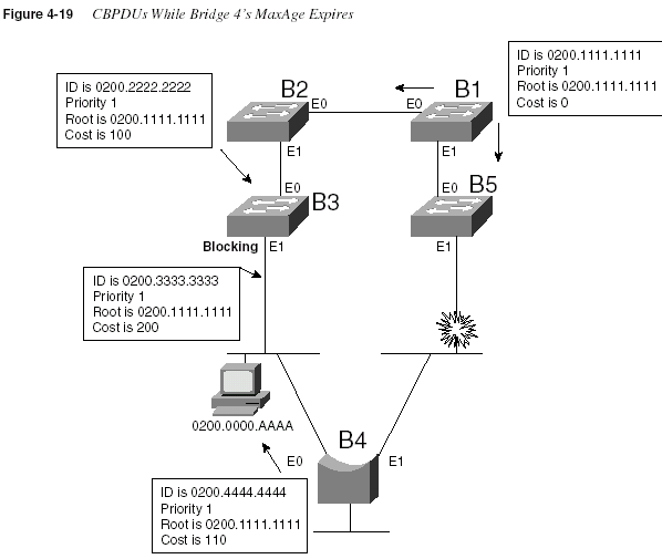
A review of the behavior of this network is useful before seeing how it is about to change. For
example, the frame on the Ethernet between Bridges 3 and 4 cannot be forwarded by Bridge 3
because it is blocking on its E1 interface. The instant Bridge 5’s E1 port fails, frames can no
longer be forwarded or received on that interface. So, during the period that MaxAge is expiring
on Bridge 4, frames can be sent by hosts on the segment between B4 and B3; then, B4 can
forward the frames, but B5 cannot. If the destination of such frames is on the opposite side of
Bridge 5, the frames are not delivered.
Only Bridge 4’s MaxAge expires. The other bridges are still receiving CBPDUs on their root
ports. After MaxAge expires, Bridge 4 will decide the following:
Step 1
My E1 port is no longer my root port.Step 2
The same root bridge is being advertised in a CBPDU on my E0port.
Step 3
No other CBPDUs are being received.168
Chapter 4: Bridges/Switches and LAN DesignStep 4
My best path (and the only path, in this case) to the root is out myE0 port; therefore, my root port is now E0.
Step 5
Because no other CBPDUs are entering my E1 port, I must be thedesignated bridge on that segment. So, I will start sending
CBPDUs on E1, adding my E0 port cost (10) to the cost of the
CBPDU received in the CBPDU entering E0 (200), for a total cost
of 210.
Step 6
I will no longer send CBPDUs out E0 because it is my root port.Figure 4-20 illustrates the result of Bridge 4’s reaction.
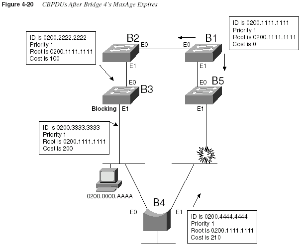
The logic used by Bridge 4 seems relatively straightforward, albeit detailed. There is a subtle
but important occurrence in this case: Both of Bridge 4’s interfaces were forwarding before the
change, and both are still forwarding. In other words, neither interface has changed state. But
Bridging, Switching, and Spanning Tree
169the process is not finished because some change to the Spanning Tree must take place for new
paths to be available. In this case, Bridge 3’s E1 will need to change from a blocking to
forwarding state, which has not occurred yet. The key part of the upcoming logic is based on
this corollary of Spanning Tree:
A change that affects the Spanning Tree results in at least one bridge interface changing
from blocking to forwarding, or vice versa.
At this point in the process, no changes to the Spanning Tree have been made, and many address
table entries refer to the path that has failed. Table 4-12 refers to the address table entries for
0200.0000.AAAA in all five bridges, showing that four of the five bridge address tables refer
to the failed path. Use Table 4-12 in conjunction with Figure 4-20 to verify that the path to this
MAC address is still invalid.
The Spanning Tree change needed is for Bridge 3 to change from blocking state to forwarding
state on its E1 interface. Bridge 3’s reaction to the lack of CBPDUs from Bridge 4 causes this
change to occur. Consider the logic that Bridge 3 uses in this case:
Step 1
I am no longer receiving any CBPDUs on my E1 interface.Step 2
After Step 1 has occurred for MaxAge time, I assume that thedesignated bridge has failed. I will become the designated bridge
on the LAN segment to which E1 is attached because no other
bridges are forwarding CBPDUs onto that segment.
Step 3
I will immediately change E1’s status from blocking to listening.That means that I will not learn addresses based on frames
entering E1. I will not forward frames entering E1, nor will I
forward frames out E1.
Step 4
I will clear entries in my address table using a short timer(typically a few seconds).
Step 5
I will send a message out my root port signifying that a topologychange is being made. (The root will eventually receive the
message.)
Table 4-12
Address Table Entries for 0200.0000.AAAA, Before Spanning Tree Has Been ChangedBridge MAC Outgoing Interface
Bridge 1 0200.0000.AAAA E1
Bridge 2 0200.0000.AAAA E0
Bridge 3 0200.0000.AAAA E0
Bridge 4 0200.0000.AAAA E0
Bridge 5 0200.0000.AAAA E1
170
Chapter 4: Bridges/Switches and LAN DesignStep 6
A Forward Delay timer is started at Step 3. When it expires, I willchange my E1 status to
learning and will begin to add addresstable entries learned from frames entering my E1 interface. I will
not forward frames out my E1 interface yet, nor will I forward
frames that enter E1 yet.
Step 7
Another Forward Delay timer was started after Step 6. When thattimer expires, I will change my E1 status to
forwarding.The Spanning Tree has now changed so that a single active path exists among all LAN
segments. The intermediate states are used in an effort to reduce the possibility of temporary
loops. Table 4-13 summarizes the intermediate states of the Spanning Tree.
The listening and learning states are intermediate states as a bridge makes a new choice about
which bridge is root. In listening state, all that matters is listening for CBPDUs so that a new
choice for root and designated bridge can be made. In learning state, MAC addresses can be
learned based on incoming frames.
One last step is necessary to complete the logic. The address table entries might not have timed
out yet (see Table 4-12). The Spanning-Tree Protocol includes the concept of notifying all
bridges that a tree change has occurred, allowing the bridges to quickly time out address table
entries. By doing so, the new path can be used very quickly.
The notification of a changing Spanning Tree is begun by Bridge 3 in Figure 4-20, in Step 5 of
its logic (shown in the list following Figure 4-20). The topology change message is received by
the root because each intervening bridge is tasked with forwarding the message. The root reacts
by setting a topology change flag in its CBPDUs for a period of time. Because all bridges
propagate these messages, all bridges will notice the
topology change flag in the CBPDU. Eachbridge can then choose to use a shorter time (for example, 2 seconds) to time out address table
entries.
Table 4-13
Spanning Tree Interface StatesState
Forward Data
Frames?
Learn MACs Based on
Received Frames?
Transitory or
Stable State?
Blocking No No Stable
Listening No No Transitory
Learning No Yes Transitory
Forwarding Yes Yes Stable
Virtual LANs
171Spanning-Tree Protocol Summary
Spanning Trees accomplish the goals of allowing physical redundancy, but with only one
currently active path through a bridged network. Spanning Tree uses the following features to
accomplish the goal:
•
All bridge interfaces eventually stabilize at either a forwarding state or a blocking state.The forwarding interfaces are considered to be a part of the Spanning Tree.
•
One of the bridges is elected as root. The process includes all bridges claiming to be root,until one is considered best by all. All root bridge interfaces are in forwarding state.
•
Each bridge receives CBPDUs from the root, either directly or forwarded by some otherbridge. Each bridge can receive more than one such message on its interfaces, but the port
in which the least-cost CBPDU is received is called the root port of a bridge, and that port
is placed in forwarding state.
•
For each LAN segment, one bridge sends the forwarded CBPDU with the lowest cost.That bridge is the designated bridge for that segment. That bridge’s interface on that
segment is placed in forwarding state.
•
All other interfaces are placed in blocking state.•
The root sends CBPDUs every Hello time seconds. The other bridges expect to receivecopies of these CBPDUs so that they know that nothing has changed. Hello time is defined
in the CBPDU itself, so all bridges use the same value.
•
If a bridge does not receive a CBPDU for MaxAge time, it begins the process of causingthe Spanning Tree to change. The reaction can vary from topology to topology. (MaxAge
is defined in the CBPDU itself, so all bridges use the same value.)
•
One or more bridges decide to change interfaces from blocking to forwarding or viceversa, depending on the change in the network. If moving from blocking to forwarding,
the interim listening state is entered first. After Forward Delay time (another timer defined
in the root CBPDU), the state is changed to learning. After another Forward Delay time,
the interface is placed in forwarding state.
•
The Spanning-Tree Protocol includes these delays to help ensure that no temporary loopsoccur.
Virtual LANs
A virtual LAN (VLAN) is a broadcast domain created by one or more switches. (Cisco expects
CCNAs to have a solid command of VLAN concepts.) The VLAN is created via configuration
in the switch, or possibly configuration referred to by the switch but residing in some external
server (for example, using VLAN Membership Policy Server [VMPS]). If a design calls for
172
Chapter 4: Bridges/Switches and LAN Designthree separate broadcast domains, three switches could be used—one for each broadcast
domain. Each switch would also be connected to a router so that packets could be routed
between broadcast domains. Instead, using VLANs, one switch could be used and the switch
would treat three different sets of ports as three different broadcast domains.
Figures 4-21 and 4-22 offer a comparison of two networks, each with three broadcasts domains.
In the first case, three switches are used and no VLANs are required. Each switch treats all ports
as members of one broadcast domain. In Figure 4-22, one switch is used; the switch is
configured so that the ports are considered to be in three different broadcast domains. In both
cases, separate broadcast domains imply separate Layer 3 groupings; a router is needed for
forwarding traffic among the different Layer 3 groups.
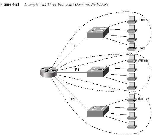
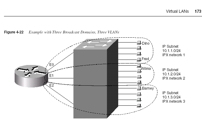
The switch in Figure 4-22 forwards frames to the router interfaces only if the frame is a
broadcast or is destined for one of the MAC addresses of the router. For example, Fred sends
frames to the router’s E0 MAC address when trying to communicate with Barney; this is
because Fred’s default router should be the router’s E0 interface’s IP address. However, when
Fred sends frames to Dino, the destination MAC address of the frame is Dino’s MAC address,
and there is no need for the switch to get the router involved. Broadcasts sent by Fred do not go
to the other VLANs because each VLAN is a separate broadcast domain.
VLANs allow easy moves, additions, and changes. For example, if Barney moved to a different
office, which was cabled to a different port on the switch, he can still be configured to be in
VLAN 3. No Layer 3 address changes are necessary, which means that no changes need be
made on Barney.
To implement VLANs in one switch, a separate address (bridging) table is used for each VLAN.
If a frame is received on a port in VLAN 2, the VLAN 2 address table will be searched. When
a frame is received, the source address is checked against the address table so that it can be
added if the address is currently unknown. Also, the destination address is checked so that a
forwarding decision can be made. For both learning and forwarding, the search is made against
the address table for that VLAN only.
174
Chapter 4: Bridges/Switches and LAN DesignImplementing VLANs with multiple switches adds more complexity that is not necessarily
obvious. Consider Figure 4-23, which uses two switches connected with a Fast Ethernet. Two
VLANs are configured.
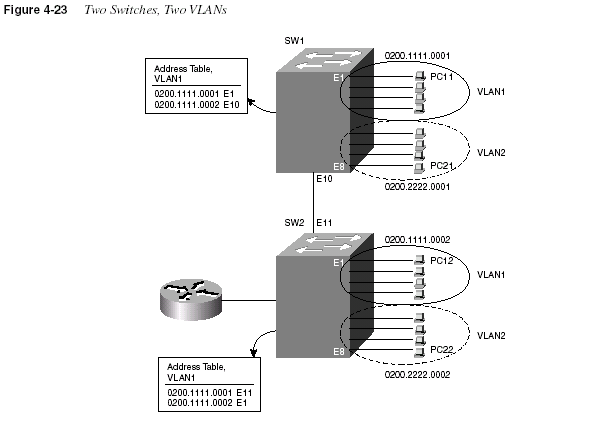
The address table for VLAN1 lists the only two MAC addresses being used in VLAN1.
Consider a frame sent from PC11 to PC12:
Step 1
PC11 generates the frame, with destination MAC0200.1111.0002.
Step 2
Switch 1 receives the frame on port E1.Step 3
Switch 1 performs address table lookup in VLAN1’s address tablebecause incoming port E1 is in VLAN1.
Step 4
Switch 1 forwards the frame out its E10 port.Step 5
Switch 2 receives the frame in its E11 port.At this point in the logic, everything seems straightforward. In the next step, however, several
choices could have been made by those who created the protocols used for LAN switching. The
choices for how Switch 2 could react to the incoming frame are as follows:
Virtual LANs
175Step 6
Switch 2 considers port E11 to be in VLAN1, so it performs tablelookup for 0200.1111.0002 in that address table.
Or . . .
Step 7
Switch 2 does not consider port E11 to be in any particular VLAN,so it does table lookup in all tables and forwards out all ports
matched.
Or . . .
Step 8
Before Switch 1 forwards the frame in Step 4, it adds a header thatidentifies the VLAN. Then, Switch 2 can look at the frame header
to identify the VLAN number and can do table lookup just in that
VLAN’s address table.
The third option for Step 6 is the one that actually was implemented. The first option would
work fine for one VLAN and is used when connecting multiple switches without using VLANs.
However, the logic in this first option fails when devices in VLAN2 send frames because their
addresses would never be found in VLAN1’s address table. The second option would work well
for unicasts, particularly because a unicast address should be found in only a single address
table. However, broadcasts would be sent on all interfaces, regardless of VLAN, which would
cause horrendous side effects for OSI Layer 3 processes. So, the third option, called
VLANtagging
, is used.ISL is one of the tagging options used in switches; Figure 4-24 shows ISL framing details.
Understanding all the values in the ISL header fields is not vital. However, there are two very
important features. First, the ISL header encapsulates the LAN frame, which lengthens the
frame. 802.1Q, the IEEE-defined Ethernet VLAN protocol, actually modifies the existing
header to accomplish the same tagging goal. The second important feature is the VLAN ID
field, which identifies the VLAN to which the encapsulated frame belongs. The source address
field in the ISL header is the address of the sending switch, and the destination address is a
special multicast address, whose first 5 bytes are 0100.0C00.00 and whose last byte is actually
comprised of the values shown in the type and user fields of Figure 4-24. The two ISL features
most important for CCNAs, however, are that ISL encapsulates the orignal frame and that there
is a VLAN-ID field in the ISL header.

176
Chapter 4: Bridges/Switches and LAN DesignTagging also can be used to reduce the number of router ports that are needed. Figure 4-23
shows the router with a single interface and a single connection to Switch 2. The same tagging
method used between switches is used for frames sent to the router so that the router knows
from which VLAN the frame originated. For frames that the router routes between the two
VLANs, the incoming frame is tagged with one VLAN ID, and the outgoing frame is tagged
with the other VLAN ID by the router before sending the frame back to the switch. Figure 4-25
shows an example network, with flows from VLAN 1 to VLAN 2. The BPDU field also is used
to identify whether the encapsulated frame is a CBPDU. Example 4-1 shows the router
configuration required to support ISL encapsulation and forwarding between these VLANs.
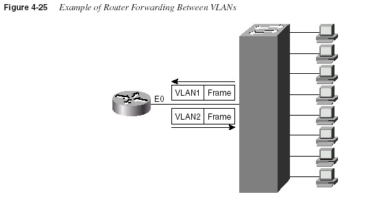
Example 4-1 shows the configuration for three subinterfaces of the Ethernet interface on the
router. Each is assigned an IP address because the interface is actually a part of three broadcast
domains, implying three IP subnets. The
encapsulation command numbers the VLANs, whichmust match the configuration for VLAN IDs in the switch.
Example 4-1
Router Configuration for ISL Encapsulation in Figure 4-25interface ethernet 0.1
ip address 10.1.1.1 255.255.255.0
encapsulation isl 1
!
interface ethernet 0.2
ip address 10.1.2.1 255.255.255.0
encapsulation isl 2
!
interface ethernet 0.3
ip address 10.1.3.1 255.255.255.0
encapsulation isl 3
LAN Switch Configuration
177Table 4-14 lists the various types of tagging used by Cisco and the types of interfaces on which
they are used:
The first three options in Table 4-14 are much easier to conceptualize. The frame headers are
encapsulated or modified to reflect a VLAN ID before the frame is sent onto the link between
switches. Before forwarding to the endpoint device, the frame header is changed back to the
original format. With LANE, there is an ATM network between switches. (LANE is a way to
make the ATM network behave like an Ethernet in some ways.) There is no tagging in LANE,
but instead, a different ATM virtual connection is used between the switches for each VLAN.
The virtual connection used implies the VLAN ID.
VLAN Summary
Many benefits can be gained from VLANs, including these:
•
With VLANs, moves, additions, and changes to device connections are easier.•
By forcing a Layer 3 routing device to be involved between VLANs, greateradministrative control can be used (better accounting, access lists, and so on).
•
Unnecessary LAN bandwidth consumption is reduced compared to a single broadcastdomain.
•
Unnecessary CPU usage is reduced by the resulting reduction in broadcast forwarding.LAN Switch Configuration
Cisco expects CCNAs to master the concepts behind LAN switching and VLANs. This mastery
includes the ability to configure IOS-based LAN switches using the IOS CLI. This section
outlines the similarities of the switch IOS CLI to the router IOS CLI, as well as contrasting the
commands, syntax, and required configuration elements unique to switches.
Not all Cisco LAN switches provide an IOS CLI interface to the network engineer. Cisco wants
its certifications to prove that the candidate knows the technology and can implement it; that
proof would be onerous if all switch families’ user interfaces were required on the CCNA exam.
Table 4-14
Frame Trunking/Tagging ProtocolsTagging Method Media
Inter-Switch Link (ISL) Fast Ethernet
802.1Q Fast Ethernet
802.10 FDDI
LAN Emulation (LANE) ATM
178
Chapter 4: Bridges/Switches and LAN DesignThis book covers some implemetation details and examples on the 1900 series switch, which is
the same (and only) switch user interface covered by the CCNA Training Path ICND course.
The similarities with the router IOS CLI far outnumber the differences. In fact, most of the
differences relate to the commands needed on a switch, which are simply not needed on a
router. The up-arrow retrieves the previous command. The ? key requests help. The Tab key
completes a parameter after you have typed in a unique set of beginning characters. The
configure terminal
command takes you from privleged EXEC mode to configuration mode.The
show running-config lists the currently used configuration. In fact, when in doubt, you canassume that the switch and router IOS CLIs are identical. The important differences will be
mentioned as appropriate in this section.
Basic 1900 Switch Configuration
On the Catalyst 1900 switch, three different configuration methods exist:
•
Menu-driven interface from the console port•
Web-based Visual Switch Manager (VSM)•
IOS command-line interface (CLI)As mentioned earlier, this book focuses on using the CLI to configure the switch. Table 4-15
lists the switch commands referred to in this section.
Table 4-15
Commands for Catalyst 1900 Switch ConfigurationCommand Description
ip address
address subnet-mask Sets the IP address for in-band management ofthe switch
ip default-gateway
Sets the default gateway so that the managementinterface can be reached from a remote network
show ip
Displays IP address configurationshow interfaces
Displays interface informationmac-address-table permanent
mac address typemodule
/portSets a permanent MAC address
mac-address-table restricted static
mac addresstype module
/port src-if-listSets a restricted static MAC address
port secure
[max-mac-count count] Sets port securityshow mac-address-table
{security} Displays the MAC address table; the securityoption displays information about the restricted or
static settings
address-violation
{suspend | disable | ignore} Sets the action to be taken by the switch if there isa security address violation
show version
Displays version informationLAN Switch Configuration
179Default 1900 Configuration
The default values vary depending on the features of the switch. The following list provides
some of the default settings for the Catalyst 1900 switch. (Not all the defaults are shown in this
example.)
•
IP address: 0.0.0.0•
CDP: Enabled•
Switching mode: FragmentFree•
100BaseT port: Auto-negotiate duplex mode•
10BaseT port: Half duplex•
Spanning Tree: Enabled•
Console password: NoneNumbering Ports (Interfaces)
The terms
interface and port both are used to describe the physical connectors on the switchhardware. For instance, the
show running-config command uses the term interface; theshow spantree
command uses the term port. The numbering of the interfaces is relativelystraightforward; the interface numbering convention for the 1912 and 1924 switches is shown
in Table 4-16. Example 4-2 shows three EXEC commands and highlights the use of the terms
interface and port.
copy tftp://10.1.1.1/config.cfg nvram
Copies a configuration file from the TFTP serverat IP address 10.1.1.1.
copy nvram tftp://10.1.1.1/config.cfg
Saves a configuration file to the TFTP server at IPaddress 10.1.1.1.
delete nvram
Removes all configuration parameters and returnsthe switch to factory default settings
Table 4-16
Catalyst 1912 and 1924 Interface/Port NumberingCatalyst 1912 Catalyst 1924
10BaseT Ports 12 total (e0/1 to e0/12) 24 total (e0/1 to e0/24)
AUI Port e0/25 e0/25
100BaseT Uplink Ports fa0/26 (port A)
fa0/27 (port B)
fa0/26 (port A)
fa0/27 (port B)
Table 4-15
Commands for Catalyst 1900 Switch Configuration (Continued)Command Description
180
Chapter 4: Bridges/Switches and LAN DesignBasic IP and Port Duplex Configuration
Two features commonly configured immediately during switch installation are TCP/IP support
and the setting of duplex on key switch ports. Switches support IP, but in a very different way
than with a router. The switch acts more like a normal IP host, with a single address/mask for
the switch and a default router. Each port/interface does not need an IP address because the
switch is not performing Layer 3 routing. In fact, if there were no need to manage the switch,
IP would not be needed on the switch at all.
The second feature typically configured at installation time is to preconfigure some ports to
always use half or full duplex rather than allow negotiation. At times, autonegotiation can
produce unpredictable results. For instance, if a device attached to the switch does not support
autonegotiation, the Catalyst switch sets the corresponding switch port to half-duplex mode by
default. If the attached device is configured for full duplex, late collision errors will occur at the
full-duplex end. To avoid this situation, manually set the duplex parameters of the switch to
match the attached device when support for autonegotiation is in question.
Example 4-2
show run Output Refers to Port e0/1 as Interface Ethernet 0/1wg_sw_d#
show running-configBuilding configuration...
Current configuration:
!
!
interface Ethernet 0/1
!
interface Ethernet 0/2
! Portions omitted for brevity...
wg_sw_d#
show spantreePort Ethernet 0/1 of VLAN1 is Forwarding
Port path cost 100, Port priority 128
Designated root has priority 32768, address 0090.8673.3340
Designated bridge has priority 32768, address 0090.8673.3340
Designated port is Ethernet 0/1, path cost 0
Timers: message age 20, forward delay 15, hold 1
! Portions omitted for brevity...
wg_sw_a#
show vlan-membershipPort VLAN Membership Type Port VLAN Membership Type
------------------------------------------------------------------
1 5 Static 13 1 Static
2 1 Static 14 1 Static
3 1 Static 15 1 Static
LAN Switch Configuration
181Similar to the router IOS, the Catalyst 1900 switch has various configuration modes. Example
4-3 shows the initial configuration of IP and duplex, with the actual prompts showing the very
familiar EXEC and configuration modes.
In the example, the duplex could have been set to one of the following modes:
•
auto—Sets autonegotiation of duplex mode. This is the default option for 100 Mbps TXports.
•
full—Sets full-duplex mode.•
full-flow-control—Sets full-duplex mode with flow control.•
half—Sets half-duplex mode. This is the default option for 10 Mbps TX ports.To verify the IP configuration and duplex settings on a given interface, use the
show ip andshow interface
commands, as seen in Example 4-4.Example 4-3
Configuration Modes for Configuring IP and Duplexwg_sw_a#
configure terminalwg_sw_a(config)#
ip address 10.5.5.11 255.255.255.0wg_sw_a(config)#
ip default-gateway 10.5.5.3wg_sw_a(config)#
interface e0/1wg_sw_a(config-if)#
duplex halfwg_sw_a(config-if)#
endwg_sw_a
Example 4-4
show ip and show interfaces Outputwg_sw_a#
show ipIP address: 10.5.5.11
Subnet mask: 255.255.255.0
Default gateway: 10.5.5.3
Management VLAN: 1
Domain name:
Name server 1: 0.0.0.0
Name server 2: 0.0.0.0
HTTP server: Enabled
HTTP port: 80
RIP: Enabled
wg_sw_a#
wg_sw_a#
sh interfacesEthernet 0/1 is Enabled
Hardware is Built-in 10Base-T
Address is 0090.8673.3341
MTU 1500 bytes, BW 10000 Kbits
802.1d STP State: Forwarding Forward Transitions: 1
Port monitoring: Disabled
Unknown unicast flooding: Enabled
Unregistered multicast flooding: Enabled
continues
182
Chapter 4: Bridges/Switches and LAN DesignNotice that there is no IP address in the
show interface output because the IP address isassociated with the entire switch, not just a single interface. The Spanning Tree state of the
interface is shown, as is the duplex setting. If duplex was mismatched with the device on the
other end, the later collisions counter would most likely increment rapidly.
Viewing and Configuring Entries in the MAC Address Table
The switching/bridging table concept discussed earlier in this chapter is called the
MAC addresstable
on the 1900 family of switches. The MAC address table contains dynamic entries, whichare learned when the switch receives frames and examines the source MAC address. Two other
variations of entries in the MAC address table are important to switch configuration and are
outlined along with dynamic entries in the following list:
•
Dynamic addresses—MAC addresses added to the MAC address table via normalbridge/switch processing. In other words, when a frame is received, the source MAC of
the frame is associated with the incoming port/interface. These entries in the table time
out with disuse and are cleared whenever the entire table is cleared.
•
Permanent MAC addresses—Via configuration, a MAC address is associated with aport, just as it would have been associated as a dynamic address. However, permanent
entries in the table never time out.
•
Restricted-static entries—Via configuration, a MAC address is configured to beassociated only with a particular port, with an additional restriction: Frames destined to
that MAC address must have entered via a particular set of incoming ports.
Description:
Duplex setting: Half duplex
Back pressure: Disabled
Receive Statistics Transmit Statistics
-------------------------------------- --------------------------------------
Total good frames 44841 Total frames 404502
Total octets 4944550 Total octets 29591574
Broadcast/multicast frames 31011 Broadcast/multicast frames 390913
Broadcast/multicast octets 3865029 Broadcast/multicast octets 28478154
Good frames forwarded 44832 Deferrals 0
Frames filtered 9 Single collisions 0
Runt frames 0 Multiple collisions 0
No buffer discards 0 Excessive collisions 0
Queue full discards 0
Errors: Errors:
FCS errors 0 Late collisions 0
Alignment errors 0 Excessive deferrals 0
Giant frames 0 Jabber errors 0
Address violations 0 Other transmit errors 0
Example 4-4
show ip and show interfaces Output (Continued)LAN Switch Configuration
183Figure 4-26 provides a simple example to show the use of permanent and restricted-static
addresses. A popular server (Server 1) is on port E0/3, and there is never a case when its MAC
address should not be in the table. So, just in case the 1024 entries in the MAC address table
are filled, which causes the switch to flush and relearn the entries, the server will remain in the
table. The payroll server is also on this switch, and only the company comptroller is allowed
access. The configuration and resulting MAC address table are shown in Example 4-5, which
follows the figure.
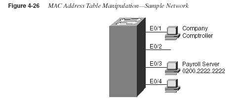
Another feature affecting the MAC address table is called
port security. Port security is a featurethat, when enabled, limits the number of MAC addresses associated with a port in the MAC
address table. In other words, there is a preset limit to the number of sources that can forward
frames into that switch port.
Example 4-5
The MAC Address Table, with Dynamic, Permanent, and Restricted-Static entrieswg_sw_a(config)#
mac-address-table permanent 0200.2222.2222 ethernet 0/3wg_sw_a(config)#
mac-address-table restricted static 0200.1111.1111 e0/4 e0/1wg_sw_a(config)#
Endwg_sw_a#
wg_sw_a#
sh mac-address-tableNumber of permanent addresses : 1
Number of restricted static addresses : 1
Number of dynamic addresses : 5
Address Dest Interface Type Source Interface List
----------------------------------------------------------------------
0200.4444.4444
Ethernet 0/1 Dynamic All00E0.1E5D.AE2F Ethernet 0/2 Dynamic All
0200.2222.2222 Ethernet 0/3 Permanent All
0200.
1111.1111 Ethernet 0/4 Static Et0/100D0.588F.B604 FastEthernet 0/26 Dynamic All
00E0.1E5D.AE2B FastEthernet 0/26 Dynamic All
00D0.5892.38C4 FastEthernet 0/27 Dynamic All
184
Chapter 4: Bridges/Switches and LAN DesignAn example is particularly useful for understanding the concept; the configuration is very
straightforward. Consider Figure 4-27, which shows a similar configuration to Figure 4-26,
except that the finance department has increased to three employees. These three employees are
on the same shared hub, which is then cabled to switch port 0/1.
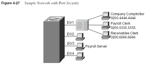
Port security can be used to restrict port 0/1 so that only three MAC addresses can source frames
that enter port 0/1—this is because only the finance department is expected to use the shared
hub. Any permanent or restricted-static MAC addresses count against this total of three.
Example 4-6 shows a sample configuration, with
show commands:Example 4-6
Port Security Examplewg_sw_a(config)#
mac-address-table permanent 0200.2222.2222 ethernet 0/3wg_sw_a(config)#
mac-address-table permanent 0200.4444.4444 ethernet 0/1wg_sw_a(config)#
mac-address-table restricted static 0200.1111.1111 e0/4 e0/1wg_sw_a(config)#
interface ethernet 0/1wg_sw_a(config-if)#
port secure max-mac-count 3wg_sw_a(config-if)#
Endwg_sw_a#
wg_sw_a#
sh mac-address-tableNumber of permanent addresses : 2
Number of restricted static addresses : 1
Number of dynamic addresses : 6
Address Dest Interface Type Source Interface List
----------------------------------------------------------------------
0200.4444.4444
Ethernet 0/1 Permanent All0200.5555.5555
Ethernet 0/1 Dynamic All0200.6666.6666
Ethernet 0/1 Dynamic All00E0.1E5D.AE2F Ethernet 0/2 Dynamic All
0200.2222.2222 Ethernet 0/3 Permanent All
0200.
1111.1111 Ethernet 0/4 Static Et0/100D0.588F.B604 FastEthernet 0/26 Dynamic All
00E0.1E5D.AE2B FastEthernet 0/26 Dynamic All
00D0.5892.38C4 FastEthernet 0/27 Dynamic All
LAN Switch Configuration
185In this example, the permanently defined MAC address of 0200.4444.444, the comptroller’s
MAC address, is always associated with port e0/1. Notice that the two new employees’ MAC
addresses are also in the MAC address table.
The
port secure max-mac-count 3 command means that a total of three addresses can belearned on this port. So, the first two addresses learned, in addition to the permanent address
that is configured, are considered to be
sticky-learned. These two addresses are considered tobe static, so that if someone came along and plugged into the finance hub, the switch would not
add that hacker’s MAC address to the MAC address table.
So what should the switch do when a fourth MAC address sources a frame that enters E0/1? An
address violation occurs when a secured port receives a frame from a new source address that,
if added to the MAC table, would cause the switch to exceed its address table size limit for that
port. When a port security address violation occurs, the options for action to be taken on a port
include suspending, ignoring, or disabling the port. When a port is suspended, it is re-enabled
when a frame containing a valid address is received. When a port is disabled, it must be
manually re-enabled. If the action is ignored, the switch ignores the security violation and keeps
the port enabled.
Use the
address-violation global configuration command to specify the action for a portaddress violation. The syntax for this command is as follows:
address-violation {suspend
| disable | ignore}Use the
no address-violation command to set the switch to its default value, which is suspend.wg_sw_a#
show mac-address-table securityAction upon address violation : Suspend
Interface Addressing Security Address Table Size
--------------------------------------------------------------
Ethernet 0/1 Enabled 3
Ethernet 0/2 Disabled N/A
Ethernet 0/3 Disabled N/A
Ethernet 0/4 Disabled N/A
Ethernet 0/5 Disabled N/A
Ethernet 0/6 Disabled N/A
Ethernet 0/7 Disabled N/A
Ethernet 0/8 Disabled N/A
Ethernet 0/9 Disabled N/A
Ethernet 0/10 Disabled N/A
Ethernet 0/11 Disabled N/A
Ethernet 0/12 Disabled N/A
Example 4-6
Port Security Example (Continued)186
Chapter 4: Bridges/Switches and LAN DesignManaging Configuration and System Files
Commands used to manage and control the configuration and system software files are slightly
different on the 1900 switch family than on IOS-based routers. One of the reasons for the
difference is that the switch does not actually run IOS—it has many features like IOS, including
the IOS CLI, but there are and probably always will be some differences. For instance, in
Example 4-7, the familiar
show version command is used to display uptime and softwarelevels, but it does not show the IOS level because IOS is not running.
Another difference is that when the configuration is changed, running-config is modified, but
the startup-config file in NVRAM is automatically updated. In other words, there is no need
for a
copy running-config startup-config command on the 1900 family of switches.Configuration files can be copied to an external TFTP server, but instead of the keyword
startup-config
, NVRAM is used.The syntax of the
copy command is slightly different than what was covered in Chapter 2,“Cisco Internetwork Operating System (IOS) Fundamentals,” relating to the router IOS
copycommand. The syntax of the command used to copy the NVRAM configuration file to host
10.1.1.1, into file mybackup.cfg is
copy nvram tftp://10.1.1.1/mybackup.cfg.Unlike the router IOS, the switch IOS CLI will not prompt for the server name or IP address or
the name of the file. Instead, the address or server host name and the file name are entered at
the command line. The fact that the command will not prompt you is certainly different than
with the router IOS. However, the same general syntax is available on the router IOS as of IOS
12.0. For instance, a similar, valid router IOS command would be
copy startup-config tftp://10.1.1.1/myrouter.cfg
.Example 4-7
show version Output Displays Switch Hardware and IOS Informationwg_sw_a#
show versionCisco Catalyst 1900/2820 Enterprise Edition Software
Version V9.00.00(12) written from 171.071.114.222
Copyright Cisco Systems, Inc. 1993-1999
DS2820-1 uptime is 2day(s) 19hour(s) 34minute(s) 41second(s)
cisco Catalyst 2820 (486sxl) processor with 2048K/1024K bytes of memory
Hardware board revision is 1
Upgrade Status: No upgrade currently in progress.
Config File Status: No configuration upload/download is in progress
25 Fixed Ethernet/IEEE 802.3 interface(s)
SLOT A:
FDDI (Fiber DAS Model), Version 00
v1.14 written from 172.031.004.151: valid
SLOT B:
100Base-TX(1 Port UTP Model), Version 0
Base Ethernet Address: 00-E0-1E-87-21-40
LAN Switch Configuration
187Table 4-17 summarizes some of the key differences between the router IOS CLI and the 1900
IOS CLI:
Basic VLAN Configuration
This section discusses the guidelines for configuring VLANs on the Cisco 1900 switch. You
should remember several items before you begin VLAN configuration:
•
The maximum number of VLANs is switch-dependent. The Catalyst 1900 supports 64VLANs with a separate Spanning Tree per VLAN.
•
VLAN1 is one of the factory-default VLANs.•
CDP and VTP advertisements are sent on VLAN1.•
Catalyst 1900 IP address is in the VLAN1 broadcast domain.•
The switch must be in VTP server mode to create, add, or delete VLANs.One term not covered yet in this list is VLAN Trunking Protocol (VTP). VTP is a Layer 2
messaging protocol that maintains VLAN configuration consistency throughout a common
administration domain. VTP accomplishes this goal by managing the additions, deletions, and
name changes of VLANs across networks. VTP minimizes misconfigurations and configuration
inconsistencies that can cause problems, such as duplicate VLAN names or incorrect VLANtype
specifications.
VTP will be covered in the next section of this chapter; to configure the VLAN features in this
section, the switches will need to be configured in VTP transparent mode.
Table 4-17
IOS CLI Differences: Router Versus 1900 SwitchFunction Router Command, Features Switch Command, Features
Finding software version show version
command; showsIOS version
show version
command; showsswitch software version
Copying configuration
files to TFTP server
copy startup-config tftp
command; router IOS prompts for
TFTP parameters
copy nvram tftp//server/file
command; switch IOS CLI does not
prompt for TFTP parameters
Updating the config file
used at reload time
copy running-config startupconfig
command
Changes to running configuration
using config mode are automatically
reflected in NVRAM config file
Erasing the config file
used at reload time
write erase
or erase startupconfigcommand
delete nvram
command188
Chapter 4: Bridges/Switches and LAN DesignTable 4-18 represents the commands covered in this section and gives a brief description of each
command’s function.
Sample Configuration for a Single Switch
When VTP is not in use (in other words, when VTP transparent mode is in use), VLAN
configuration consists of three primary tasks:
1
Enabling VTP transparent mode2
Creating the VLAN numbers and names3
Configuring each port’s assigned VLANFirst, use the
vtp global configuration command to configure VTP transparent mode. Use thevlan
global command to define each VLAN number (required) and associated name (optional).Then assign each port to its associated VLAN using the
vlan-membership interfacesubcommand. Example 4-8 shows an example, based on Figure 4-28.
Table 4-18
VLAN Command ListCommand Description
delete vtp
Resets all VTP parameters to defaults and resetsthe configuration revision number to 1
vtp
[server | transparent | client] [domaindomain-name
] [trap {enable | disable}][
password password] [pruning {enable |disable
}]Defines VTP parameters
vtp trunk pruning-disable
vlan-list Disables pruning for specified VLANs on aparticular trunk interface (interface subcommand)
show vtp
Displays VTP statustrunk
[on | off | desirable | auto | nonegotiate] Configures a trunk interfaceshow trunk
Displays trunk statusvlan
vlan# name vlanname Defines a VLAN and its nameshow vlan
Displays VLAN informationvlan-membership static
vlan# Assigns a port to a VLANshow vlan-membership
Displays VLAN membershipshow spantree
vlan# Displays Spanning Tree information for a VLANLAN Switch Configuration
189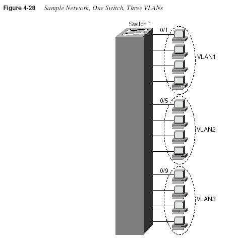
Example 4-8
Single-Switch VLAN Configuration Matching Figure 4-28switch(config)#
vtp transparent domain dummyswitch(config)#
vlan 2 name VLAN2switch1(config)#
vlan 3 name VLAN3switch1(config)#
interface e 0/5switch1(config-if)#
vlan-membership static 2switch1(config-if)#
interface e 0/6switch1(config-if)#
vlan-membership static 2switch1(config-if)#
interface e 0/7switch1(config-if)#
vlan-membership static 2switch1(config-if)#
interface e 0/8switch1(config-if)#
vlan-membership static 2switch1(config-if)#
interface e 0/9switch1(config-if)#
vlan-membership static 3switch1(config-if)#
interface e 0/10switch1(config-if)#
vlan-membership static 3switch1(config-if)#
interface e 0/11switch1(config-if)#
vlan-membership static 3switch1(config-if)#
interface e 0/12switch1(config-if)#
vlan-membership static 3190
Chapter 4: Bridges/Switches and LAN DesignNotice that some configuration seems to be missing. VLAN 1, with name VLAN1, is not
configured because it is configured automatically. In fact, the name cannot be changed. Also,
any ports without a specific static VLAN configuration are considered to be in VLAN1. Also,
the IP address of the switch is considered to be in VLAN1’s broadcast domain. Ports 5 through
8 are statically configured for VLAN2; similarly, VLAN3 comprises ports 9 through 12. In
addition, the yet-unexplained VTP is set to transparent mode, with a meaningless domain name
of
dummy—this setting is not important (yet); it simply must be set.After the VLAN is configured, the parameters for that VLAN should be confirmed to assure
validity. To verify the parameters of a VLAN, use the s
how vlan vlan# privileged EXECcommand to display information about a particular VLAN. Use
show vlan to show allconfigured VLANs. Example 4-9 demonstrates the
show command output, which shows theswitch ports assigned to the VLAN.
Other VLAN parameters shown in Example 4-9 include the type (default is Ethernet), SAID
(used for FDDI trunk), MTU (default is 1500 for Ethernet VLAN), Spanning-Tree Protocol (the
1900 supports only the 802.1D Spanning-Tree Protocol standard), and other parameters used
for Token Ring or FDDI VLANs.
Sample Configuration for Multiple Switches
To allow VLANs to span multiple switches, you must configure
trunks to interconnect theswitches. Trunks are simply LANs connecting switches. Cisco calls the use of a trunking
protocol such as ISL over such a link trunking, so the command to enable these protocols is
called
trunk.Use the
trunk interface configuration command to set a Fast Ethernet port to trunk mode. Onthe Catalyst 1900, the two Fast Ethernet ports are interfaces fa0/26 and fa0/27. Enabling and
defining the type of trunking protocol can be done statically, or dynamically for ISL using the
Example 4-9
show vlan OutputSwitch1#
sh vlan 3VLAN Name Status Ports
-------------------------------------------------
3 VLAN3 Enabled 9-12
-------------------------------------------------
VLAN Type SAID MTU Parent RingNo BridgeNo Stp Trans1 Trans2
--------------------------------------------------------------------------------
3 Ethernet 100003 1500 0 1 1 Unkn 0 0
--------------------------------------------------------------------------------
LAN Switch Configuration
191Dynamic Inter-Switch Link (DISL) protocol. DISL manages automatic ISL trunk negotiation.
The syntax for the
trunk fast Ethernet interface configuration subcommand is as follows:switch(config)#
trunk [on | off | desirable | auto | nonnegotiate]The options for the
trunk command function are as follows:•
on—Configures the port into permanent ISL trunk mode and negotiates with theconnected device to convert the link to trunk mode.
•
off—Disables port trunk mode and negotiates with the connected device to convert thelink to nontrunk.
•
desirable—Triggers the port to negotiate the link from nontrunking to trunk mode. Theport negotiates to a trunk port if the connected device is either in the
on, desirable, or autostate. Otherwise, the port becomes a nontrunk port.
•
auto—Enables a port to become a trunk only if the connected device has the state set toon
or desirable.•
nonegotiate—Configures a port to permanent ISL trunk mode, and no negotiation takesplace with the partner.
As seen in the list, many options exist. Choices for these options are mostly personal
preference. Because trunks seldom change, my preference is to configure either
on or off.Figure 4-29 and Example 4-10 provide an expanded sample network, along with the additional
configuration required.
Notice that not only was trunking enabled on both Fast Ethernet ports, but each of the three
VLANs was statically configured on those ports. By also configuring the VLANs, the switch
treats the trunk ports as part of those VLANs. The router also must be configured to support
ISL, as seen earlier in this chapter.
To verify a trunk configuration, use the
show trunk privileged EXEC command to display thetrunk parameters, as demonstrated in Example 4-10. The syntax is as follows:
Switch1(config)#
show trunk [a | b]The parameters a and b represent the Fast Ethernet ports:
•
Port a represents Fast Ethernet 0/26.•
Port b represents Fast Ethernet 0/27.192
Chapter 4: Bridges/Switches and LAN Design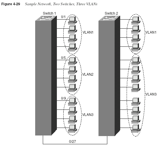
Example 4-10
Two Switch VLAN Configurations Matching Figure 4-29Switch1(config)#
interface fa 0/26switch1(config-if)#
trunk onswitch1(config-if)#
vlan-membership static 1switch1(config-if)#
vlan-membership static 2switch1(config-if)#
vlan-membership static 3switch1(config-if)#
interface fa 0/27switch1(config-if)#
trunk onswitch1(config-if)#
vlan-membership static 1switch1(config-if)#
vlan-membership static 2switch1(config-if)#
vlan-membership static 3LAN Switch Configuration
193Example 4-11 shows a sample of the
show trunk command, as well as the show vlanmembershipcommand:
Use the
show spantree privileged EXEC command to display the Spanning-Tree Protocolconfiguration status of the switch, as demonstrated in Example 4-12.
Example 4-11
show trunk OutputSwitch1#
show trunk aDISL state: Off, Trunking: On, Encapsulation type: ISL
Switch1#
show vlan-membershipPort VLAN Membership Type Port VLAN Membership Type
-----------------------------------------------------------------------------
1 1 Static 14 2 Static
2 1 Static 15 2 Static
3 1 Static 16 1 Static
4 1 Static 17 1 Static
5 2 Static 18 1 Static
6 2 Static 19 1 Static
7 2 Static 20 1 Static
8 2 Static 21 1 Static
9 3 Static 22 1 Static
10 3 Static 23 1 Static
11 3 Static 24 1 Static
12 3 Static AUI 1 Static
13 1 Static
A 1-3 Static
B 1-3 Static
Example 4-12
show spantree OutputSwitch1#
show spantree 1VLAN1 is executing the IEEE compatible Spanning-Tree Protocol
Bridge Identifier has priority 32768, address 0050.F037.DA00
Configured hello time 2, max age 20, forward delay 15
Current root has priority 0, address 00D0.588F.B600
Root port is FastEthernet 0/27, cost of root path is 10
Topology change flag not set, detected flag not set
Topology changes 53, last topology change occurred 0d00h17m14s ago
Times: hold 1, topology change 8960
hello 2, max age 20, forward delay 15
Timers: hello 2, topology change 35, notification 2
Port Ethernet 0/1 of VLAN1 is Forwarding
Port path cost 100, Port priority 128
Designated root has priority 0, address 00D0.588F.B600
Designated bridge has priority 32768, address 0050.F037.DA00
Designated port is Ethernet 0/1, path cost 10
Timers: message age 20, forward delay 15, hold 1
194
Chapter 4: Bridges/Switches and LAN DesignExample 4-12 displays various Spanning Tree information for VLAN1, including the
following:
•
Port e0/1 is in the forwarding state for VLAN1.•
The root bridge for VLAN1 has a bridge priority of 0, with a MAC address of00D0.588F.B600.
•
The switch is running the IEEE 802.1d Spanning-Tree Protocol.VLAN Trunking Protocol (VTP)
VTP is a Layer 2 messaging protocol that maintains VLAN configuration consistency
throughout a common administration domain. VTP manages the additions, deletions, and name
changes of VLANs across multiple switches. VTP minimizes misconfigurations and
configuration inconsistencies that can cause problems, such as duplicate VLAN names or
incorrect VLAN-type specifications.
VTP distributes and synchronizes identifying information about VLANs configured throughout
a switched network. Configurations made to a single switch, which is called the VTP server, are
propagated across trunk links to all switches in the same VTP domain. VTP allows switched
network solutions to scale to large sizes by reducing the manual configuration needs in the
network.
The VTP domain is created by having each switch in the domain configure the same domain
name. The network administrator chooses which switches are in the same domain by deciding
which switches share common VLANs. One switch is chosen and then configured as the VTP
server; then, the others are configured as clients for full VTP operation. (VTP transparent mode,
a third option, will be covered shortly.)
How VTP Works
VTP advertisements are flooded throughout the management domain every 5 minutes, or
whenever there is a change in VLAN configurations. Included in a VTP advertisement is a
configuration revision number, as well as VLAN names and numbers, and information about
which switches have ports assigned to each VLAN. By configuring the details on one server and
propagating the information via advertisements, all switches know the names and numbers of
all VLANs.
One of the most important components of the VTP advertisements is the
configurationrevision number
. Each time a VTP server modifies its VLAN information, it increments theconfiguration revision number by one. The VTP server then sends out a VTP advertisement that
includes the new configuration revision number. When a switch receives a VTP advertisement
with a larger configuration revision number, it updates its VLAN configuration. Figure 4-30
illustrates how VTP operates in a switched network.
LAN Switch Configuration
195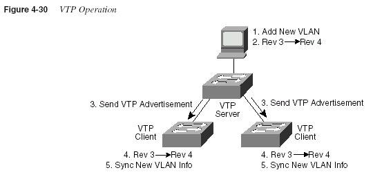
VTP operates in one of three modes: server mode, client mode, or transparent mode. VTP
servers can create, modify, and delete VLANs and other configuration parameters for the entire
VTP domain; this information in turn is propagated to the VTP clients in that same domain.
VTP servers save VLAN configurations in the Catalyst NVRAM, whereas in clients, the VLAN
configuration is not stored. When you make a change to the VLAN configuration on a VTP
server, the change is dynamically propagated to all switches in the VTP domain. VTP messages
are transmitted by the server out all trunk connections.
A VTP client cannot create, change, or delete VLANs, nor can it save VLAN configurations in
nonvolatile memory. So, why be a VTP client? Well, if one person or department is in control
of several switches, then using VTP can save configuration time and effort. The VTP-learned
configuration information is kept in the running configuration on each client switch, so even if
the server fails, VLAN configuration information is still available to the clients.
VTP transparent mode is used when a switch does not need or want to participate in VTP, but
is willing to pass VTP advertisements to other switches. A switch in transparent mode forwards
VTP advertisements received from other switches that are part of the same management
domain. A switch configured in VTP transparent mode can create, delete, and modify VLANs,
but the changes are not transmitted to other switches in the domain; they affect only the local
switch. Choosing to use transparent mode is typical when there is a need for distributed
administrative control of the switches, in spite of the fact that they each control parts of the same
VLANs. That administrative need is relatively rare. Also, VTP pruning, a topic covered later in
this chapter, is available only to VTP servers and clients, which is another compelling reason to
not use VTP transparent mode.
196
Chapter 4: Bridges/Switches and LAN DesignTable 4-19 offers a comparative overview of the three VTP modes.
VTP Pruning
Because ISL trunk lines carry VLAN traffic for all VLANs, some traffic might be needlessly
broadcast across links that do not need to carry that traffic. VTP pruning uses VLAN
advertisements to determine when a trunk connection is flooding traffic needlessly. By default,
a trunk connection carries traffic for all VLANs in the VTP management domain. Commonly,
some switches in an enterprise network do not have local ports configured in each VLAN. In
Figure 4-31, Switches 1 and 4 support ports statically configured in VLAN 10. As illustrated,
with VTP pruning enabled, when Station A sends a broadcast, the broadcast is flooded only
toward any switch with ports assigned to VLAN 10. As a result, broadcast traffic from Station
A is not forwarded to Switches 3, 5, and 6 because traffic for VLAN 10 has been pruned on the
links indicated on Switches 2 and 4.
VTP pruning increases available bandwidth by restricting flooded traffic to those trunk links
that the traffic must use to access the appropriate network devices. VTP pruning is one of the
two most compelling reasons to use VTP—the other is to make VLAN configuration easier and
more consistent.
VLAN Configuration Using VTP
Basic VLAN configuration, with the switch in VTP transparent mode, has already been
covered. This section focuses on VTP configuration for client and server and shows an example
configuration for two switches: one the VTP server and one a VTP client.
Table 4-19
VTP ModesFunction Server Mode Client Mode
Transparent
Mode
Originates VTP advertisements Yes No No
Processes received advertisements and
synchronizes VLAN configuration
information with other switches
No Yes No
Forwards VTP advertisements received
in a trunk
No Yes Yes
Saves VLAN configuration in NVRAM Yes No Yes
Can create, modify, or delete VLANs
using configuration commands
Yes No Yes
LAN Switch Configuration
197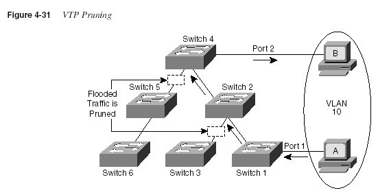
Several parameters can be set for VTP operation on a switch. The server, client, and transparent
mode options have already been discussed. Several other important parameters are allowed. The
default VTP configuration parameters for the Catalyst 1900 switch are as follows:
•
VTP domain name: None•
VTP mode: Server•
VTP password: None•
VTP pruning: Disabled•
VTP trap: EnabledThe VTP domain name can be specified or learned. By default, the domain name is not set,
and the switch is set to the VTP server mode. If a switch using the defaults receives a VTP
advertisement with a domain name, then that switch assumes the use of that domain name.
However, if a switch is configured with one domain name and it receives an advertisement that
includes a different domain name, the advertisement is ignored. One advantage of this process
is that with default configuration on all switches, VTP will be enabled, all switches will be in
server mode, but all will be listening for advertisements—thus, VTP will still work. If one
switch is configured with the domain name, then it will propagate to the other switches. Or, if
multiple domains are in use, simply configure each switch with the correct name, and the other
domains’ VTP updates will be ignored.
A password can be set for the VTP management domain. The password entered must be the
same for all switches in the domain. If you configure a VTP password, VTP does not function
properly unless you assign the same password to each switch in the domain.
198
Chapter 4: Bridges/Switches and LAN DesignVTP pruning eligibility
defines where VTP pruning is enabled for the entire managementdomain
. Enabling or disabling VTP pruning on a VTP server propagates the change throughoutthe management domain. If pruning is enabled, all VLANs are pruned
except VLAN1; VLAN1is used for propagating VTP advertisements, so any pruning would make it difficult to graft the
branches back into the tree. Pruning can be globally enabled in the domain and then selectively
disabled for specified VLANs on specified trunks using the
vtp trunk pruning-disable vlanlisttrunk interface subcommand.
Enabling a VTP trap causes an SNMP message to be generated every time a new VTP message
is sent out. VTP trap is enabled by default.
Examples 4-13 and 4-14 show the complete configuration of Switch1 and Switch2 from
Figure 4-29. Switch1 will be the VTP server.
Example 4-13
Switch1 Complete Configuration as VTP ServerSwitch1#
configure terminalSwitch1(config)#
ip address 10.5.5.11 255.255.255.0Switch1(config)#
ip default-gateway 10.5.5.3Switch1(config)#
vtp server domain Hartsfield pruning enableSwitch1(config)#
vlan 2 name VLAN2switch1(config)#
vlan 3 name VLAN3switch1(config)#
interface e 0/5switch1(config-if)#
vlan-membership static 2switch1(config-if)#
interface e 0/6switch1(config-if)#
vlan-membership static 2switch1(config-if)#
interface e 0/7switch1(config-if)#
vlan-membership static 2switch1(config-if)#
interface e 0/8switch1(config-if)#
vlan-membership static 2switch1(config-if)#
interface e 0/9switch1(config-if)#
vlan-membership static 3switch1(config-if)#
interface e 0/10switch1(config-if)#
vlan-membership static 3switch1(config-if)#
interface e 0/11switch1(config-if)#
vlan-membership static 3switch1(config-if)#
interface e 0/12switch1(config-if)#
vlan-membership static 3Switch1(config)#
interface fa 0/26switch1(config-if)#
trunk onswitch1(config-if)#
vlan-membership static 1switch1(config-if)#
vlan-membership static 2switch1(config-if)#
vlan-membership static 3switch1(config-if)#
interface fa 0/27switch1(config-if)#
trunk onswitch1(config-if)#
vlan-membership static 1switch1(config-if)#
vlan-membership static 2switch1(config-if)#
vlan-membership static 3LAN Switch Configuration
199Several items are particularly important in these configurations. The
vtp global commandin Example 4-13 shows Switch1 as the server, with domain
Hartsfield. No password is usedin this case. Switch2 is not configured with the domain name but will learn it with the first
advertisement. Missing from Example 4-14 is the definition of the VLANs, which is not only
unnecessary but also is not allowed when in VTP client mode. And, because pruning was
enabled in the
vtp command on Switch1, VTP prunes VLAN3 from Switch2 because Switch2has no ports in VLAN3. VLAN3 broadcasts received by Switch1 are not forwarded to Switch2.
To verify a recent configuration change, or to just view the VTP configuration information, use
the
show vtp privileged EXEC command, as demonstrated in Example 4-15. Also displayed isthe IP address of the device that last modified the configuration and a time stamp of the time the
modification was made. VTP has two versions: VTP Version 1 supports only Ethernet; VTP
Version 2 supports Ethernet and Token Ring.
Example 4-14
Switch2 Complete Configuration as VTP ClientSwitch2#
configure terminalSwitch2(config)#
ip address 10.5.5.12 255.255.255.0Switch2(config)#
ip default-gateway 10.5.5.3Switch2(config)#
vtp clientswitch2(config)#
interface e 0/5switch2(config-if)#
vlan-membership static 2switch2(config-if)#
interface e 0/6switch2(config-if)#
vlan-membership static 2switch2(config-if)#
interface e 0/7switch2(config-if)#
vlan-membership static 2switch2(config-if)#
interface e 0/8switch2(config-if)#
vlan-membership static 2switch2(config-if)#
interface e 0/9switch2(config-if)#
vlan-membership static 2switch2(config-if)#
interface e 0/10switch2(config-if)#
vlan-membership static 2switch2(config-if)#
interface e 0/11switch2(config-if)#
vlan-membership static 2switch2(config-if)#
interface e 0/12switch2(config-if)#
vlan-membership static 2switch2(config-if)#
interface fa 0/27switch2(config-if)#
trunk onswitch2(config-if)#
vlan-membership static 1switch2(config-if)#
vlan-membership static 2Example 4-15
show vtp OutputSwitch1#
show vtpVTP version: 1
Configuration revision: 4
Maximum VLANs supported locally: 1005
Number of existing VLANs: 3
VTP domain name:Hartsfield
VTP password:
VTP operating mode: Server
VTP pruning mode: Enabled
VTP traps generation: Enabled
Configuration last modified by: 10.5.5.3 at 00-00-0000 00:00:00
200
Chapter 4: Bridges/Switches and LAN DesignFoundation Summary
The Foundation Summary is a collection of tables and figures that provide a convenient review
of many key concepts in this chapter. For those of you already comfortable with the topics in
this chapter, this summary could help you recall a few details. For those of you who just read
this chapter, this review should help solidify some key facts. For any of you doing your final
prep before the exam, these tables and figures will be a convenient way to review the day before
the exam.
Figure 4-32 summarizes the various LAN header formats.
Table 4-20 summarizes the fields used for identifying the types of data contained in a frame.
Table 4-20
Protocol Type Fields in LAN HeadersField Name Length LAN Type Comments
Ethernet Type 2 bytes Ethernet RFC 1700 (Assigned Numbers RFC)
lists the values. Xerox owns the
assignment process.
802.2 DSAP and
SSAP
1 byte each IEEE Ethernet,
IEEE Token Ring,
ANSI FDDI
The IEEE Registration Authority
controls the assignment of valid values.
The source SAP (SSAP) and
destination SAP (DSAP) do not have to
be equal, so 802.2 calls for the sender’s
protocol type (SSAP) and the
destination’s type (DSAP).
SNAP Protocol 2 bytes IEEE Ethernet,
IEEE Token Ring,
ANSI FDDI
Uses EtherType values. Used only when
DSAP is hex AA. It is needed because
the DSAP and SSAP fields are only 1
byte in length.
Foundation Summary
201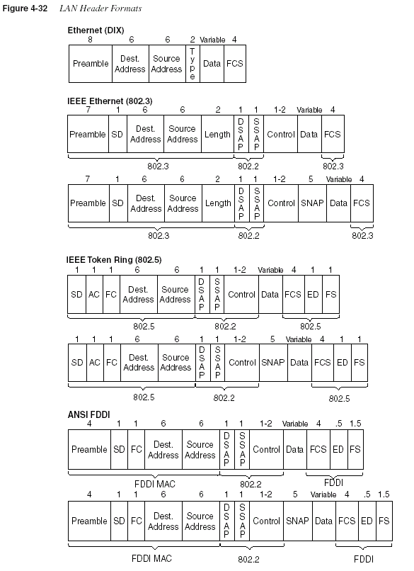
202
Chapter 4: Bridges/Switches and LAN DesignTable 4-21 lists the specification that defines the Media Access Control (MAC) and Logical
Link Control (LLC) sublayers of the three LAN types, for comparison.
Table 4-22 lists the key Ethernet specifications and several related details about the operation
of each.
Table 4-21
MAC and LLC Details for Three Types of LANsName
MAC Sublayer
Spec
LLC Sublayer
Spec
Other Comments
Ethernet Version 2
(DIX Ethernet)
Ethernet — This spec is owned by Digital,
Intel, and Xerox.
IEEE Ethernet IEEE 802.3 IEEE 802.2 This also is popularly called
802.3 Ethernet.
Token Ring IEEE 802.5 IEEE 802.2 IBM helped with development
before the IEEE took over.
FDDI ANSI X3T9.5 IEEE 802.2 ANSI liked 802.2, so it just
refers to the IEEE spec.
Table 4-22
Ethernet StandardsStandard
MAC Sublayer
Specification
Maximum Cable
Length Cable Type
Pairs
Required
10Base5 802.3 500 m
1 50 ohm thick coaxialcable
—
10Base2 802.3 185 m
1 50 ohm thin coaxialcable
—
10BaseT 802.3 100 m
1 Category 3, 4, or 5UTP
2
10BaseFL 802.3 2000 m
2 Fiber 1100BaseTx 802.3u 100 m
2 Category 5 UTP 2100BaseT4 802.3u 100 m
2 Category 3 UTP 4100BaseT2 802.3u 100 m
2 Category 3, 4, or 5UTP
2
100BaseFx 802.3u 400/2000 m
3 Multimode fiber 1100BaseFx 802.3u 10,000 m Single-mode fiber 1
1000BaseSx 802.3z 220-550 m Multimode fiber 1
Foundation Summary
2031. For entire bus
2. From device to hub/switch
3. Numbers shown are for half/full duplex
The internal processing methods of LAN switches are listed in Table 4-23.
Table 4-24 lists several features relating to segmenting LANs with bridges, switches, and
routers.
1000BaseLx 802.3z 3000 m Single-mode or
multimode fiber
1
1000BaseCx 802.3z 25 m Shielded copper 2
1000BaseT 802.3ab 100 m Category 5 UTP 2
Table 4-23
Switch Internal ProcessingSwitching Method Description
Store-and-forward The switch fully receives all bits in the frame (store) before forwarding the
frame (forward). This allows the switch to check the FCS before forwarding
the frame. (FCS is in the Ethernet trailer.)
Cut-through The switch performs the address table lookup as soon as the destination
address field in the header is received. The first bits in the frame can be sent
out the outbound port before the final bits in the incoming frame are received.
This does not allow the switch to discard frames that fail the FCS check.
(FCS is in the Ethernet trailer.)
FragmentFree This performs like cut-through, but the switch waits for 64 bytes to be
received before forwarding the first bytes of the outgoing frame. According
to Ethernet specifications, collisions should be detected during the first 64
bytes of the frame; frames in error due to collision are not forwarded. The
FCS still cannot be checked.
Table 4-24
Comparison of Segmentation OptionsFeature Bridging Switching Routing
Forwards LAN broadcasts? Yes Yes No
Forwards LAN multicasts? Yes Yes; can be
optimized
with CGMP
No
1Table 4-22
Ethernet Standards (Continued)Standard
MAC Sublayer
Specification
Maximum Cable
Length Cable Type
Pairs
Required
continues
204
Chapter 4: Bridges/Switches and LAN Design1. Routers can forward IP multicast packets, if configured to do so. However, this does not mean that the LAN
multicast frame is forwarded.
Table 4-25 lists features that must be interpreted within the following context: “If I migrated
from a single Ethernet segment to a network with two segments separated by a bridge/switch/
router, and if traffic loads and destinations stayed constant, the result would be _______.”
Table 4-26 summarizes the reasons why Spanning Tree places a port into forwarding or
blocking state:
OSI layer used when making forwarding decision Layer 2 Layer 2 Layer 3
Internal processing variants Store-andforward
Store-andforward,
cutthrough,
FragmentFree
Store-andforward
Frame/packet fragmentation allowed? No No Yes
Multiple concurrent equal-cost paths to same
destination allowed?
No No Yes
Table 4-25
Comparison of a Single Segment to Multiple SegmentsFeature Bridging Switching Routing
Greater cabling distances allowed Yes Yes Yes
Decrease in collisions, assuming equal traffic loads Yes Yes Yes
Decreased adverse impact of broadcasts No No Yes
Decreased adverse impact of multicasts No Yes, with
CGMP
Yes
Increase in bandwidth Yes Yes Yes
Filtering on Layer 2 header allowed Yes Yes Yes
Filtering on Layer 3 header allowed No No Yes
Table 4-26
Spanning Tree—Reasons for Forwarding or BlockingCharacterization
of Port Spanning Tree State Explanation
All root bridge’s ports Forwarding The root bridge is always the designated bridge
on all connected segments.
Each nonroot bridge’s
root port
Forwarding The root port is the port receiving the lowestcost
CBPDU from the root.
Table 4-24
Comparison of Segmentation Options (Continued)Feature Bridging Switching Routing
Foundation Summary
205Table 4-27 summarizes the intermediate states of the Spanning Tree.
Table 4-28 lists the various types of tagging used by Cisco and the types of interfaces on which
they are used.
Each LAN’s designated
bridge
Forwarding The bridge forwarding the lowest-cost CBPDU
onto the segment is the designated bridge.
All other ports Blocking The port is not used for forwarding frames, nor
are any frames received on these interfaces
considered for forwarding.
Table 4-27
Spanning Tree Interface StatesState
Forward Data
Frames?
Learn MACs Based on
Received Frames?
Transitory or
Stable State?
Blocking No No Stable
Listening No No Transitory
Learning No Yes Transitory
Forwarding Yes Yes Stable
Table 4-28
Frame Trunking/Tagging ProtocolsTagging Method Media
Inter-Switch Link (ISL) Fast Ethernet
802.1Q Fast Ethernet
802.10 FDDI
LAN Emulation (LANE) ATM
Table 4-26
Spanning Tree—Reasons for Forwarding or Blocking (Continued)Characterization
of Port Spanning Tree State Explanation
206
Chapter 4: Bridges/Switches and LAN DesignQ&A
As mentioned in Chapter 1, “All About the Cisco Certified Network Associate Certification,”
the questions and scenarios in this book are more difficult than what you should experience on
the actual exam. The questions do not attempt to cover more breadth or depth than the exam;
however, they are designed to make sure that you know the answer. Rather than allowing you
to derive the answer from clues hidden inside the question itself, the questions challenge your
understanding and recall of the subject. Questions from the “Do I Know This Already?” quiz
from the beginning of the chapter are repeated here to ensure that you have mastered the
chapter’s topic areas. Hopefully, these questions will help limit the number of exam questions
on which you narrow your choices to two options and then guess.
The answers to these questions can be found in Appendix A, on page 718.
1
What do the letters MAC stand for? What other terms have you heard to describe the sameor similar concept?
2
Name two benefits of LAN segmentation using transparent bridges.3
What routing protocol does a transparent bridge use to learn about Layer 3 addressinggroupings?
4
What settings are examined by a bridge or switch to determine which should be elected asroot of the Spanning Tree?
5
Define the term VLAN.6
Assume that a building has 100 devices attached to the same Ethernet. These users thenare migrated onto two separate shared Ethernet segments, each with 50 devices, with a
transparent bridge in between. List two benefits that would be derived for a typical user.
7
What standards body owns the process of ensuring unique MAC addresses worldwide?8
Assume that a building has 100 devices attached to the same Ethernet. These devices aremigrated to two different shared Ethernet segments, each with 50 devices. The two
segments are connected to a Cisco LAN switch to allow communication between the two
sets of users. List two benefits that would be derived for a typical user.
9
Name two of the methods of internal switching on typical switches today. Which providesless latency for an individual frame?
10
What is the distance limitation of 10BaseT? 100BaseTX?11
Describe how a transparent bridge decides whether it should forward a frame, and tell howit chooses the interface out which to forward the frame.
12
How fast is Fast Ethernet?13
Describe the benefit of the Spanning-Tree Protocol as used by transparent bridges andswitches.
Q&A
20714
If a switch hears three different configuration BPDUs from three different neighbors onthree different interfaces, and if all three specify that Bridge 1 is the root, how does the
switch choose which interface is its root port?
15
How does a transparent bridge build its address table?16
How many bytes long is a MAC address?17
Assume that a building has 100 devices attached to the same Ethernet. These users thenare migrated onto two separate Ethernet segments, each with 50 devices and separated by
a router. List two benefits that would be derived for a typical user.
18
Does a bridge/switch examine just the incoming frame’s source MAC, destination MAC,or both? Why does it examine the one(s) it examines?
19
Define the term collision domain.20
When a bridge or switch using Spanning-Tree Protocol first initializes, who does it assertshould be the root of the tree?
21
Name the three reasons why a port is placed in forwarding state as a result of SpanningTree.
22
Define the difference between broadcast and multicast MAC addresses.23
Excluding the preamble and starting delimiter fields, but including all other Ethernetheaders and trailers, what is the maximum number of bytes in an Ethernet frame?
24
Define the term broadcast domain.25
Describe the benefits of creating three VLANs of 25 ports each, versus a single VLAN of75 ports, in each case using a single switch. Assume that all ports are switched ports (each
port is a different collision domain).
26
If two Cisco LAN switches are connected using Fast Ethernet, what VLAN trunkingprotocols could be used? If only one VLAN spanned both switches, is a VLAN trunking
protocol needed?
27
Explain the function of the loopback and collision detection features of an Ethernet NICin relation to half-duplex and full-duplex operation.
28
Name the three interface states that the Spanning-Tree Protocol uses, other thanforwarding. Which of these states is transitory?
29
What are the two reasons that a nonroot bridge/switch places a port in forwarding state?30
Can the root bridge/switch ports be placed in blocking state?31
How many IP addresses must be configured for network management on a Cisco Catalyst1900 switch if eight ports are to be used and with three VLANs?
208
Chapter 4: Bridges/Switches and LAN Design32
What command on a 1900 series switch would cause the switch to block frames destinedto 0200.7777.7777, entering interface 0/5, from going out port 0/6?
33
What Catalyst 1900 switch command displays the version of IOS running in the switch?34
What does the Catalyst 1900 switch command address violation disable do?35
What command erases the startup config in a Catalyst 1900 switch?36
Configuration is added to the running configuration in RAM when commands are typedin Catalyst 1900 configuration mode. What causes these commands to be saved into
NVRAM?
37
How do EXEC and configuration commands refer to the two Fast Ethernet ports on aCatalyst 1912 switch?
38
What Catalyst 1900 switch command displays the switching table?39
What does VTP do, and what does the abbreviation stand for?40
Name the three VTP modes. Which of these does not allow VLANs to be added ormodified?
41
What Catalyst 1900 switch command assigns a port to a particular VLAN?42
What Catalyst 1900 switch command creates VLAN 10 and assigns it a name ofbigbadvlan?
43
What Catalyst 1900 switch command lists the details about VLAN number 10?44
What Catalyst 1900 switch command configures ISL trunking on fastethernet port 26 sothat as long as the switch port on the other end of the trunk is not disabled (off) or
configured to not negotiate to become a trunk, the trunk will definitely be placed in
trunking mode?
45
What type of VTP mode allows a switch to create VTP advertisements?